UM1724 Rev 14 47/68
UM1724 Hardware layout and configuration
67
Warning: PWM is not supported by D10 on STM32L010 and STM32L073 since the
timer is not available on PB6.
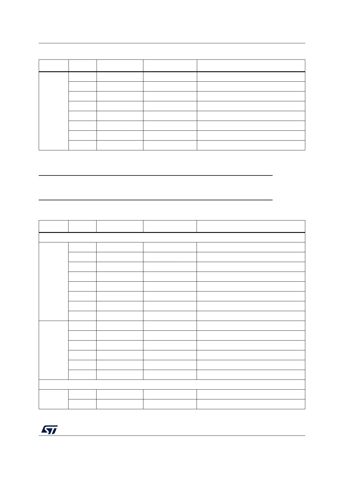
CN9 digital
8D7 PA8 -
7 D6 PB10 TIM2_CH3
6 D5 PB4 TIM3_CH1
5 D4 PB5 -
4 D3 PB3 TIM2_CH2
3D2 PA10 -
2 D1 PA2 USART2_TX
1 D0 PA3 USART2_RX
1. Refer to Table 10: Solder bridges for details.
Table 18. ARDUINO
®
connectors on NUCLEO-L010RB and NUCLEO-L073RZ (continued)
Connector Pin Pin name STM32 pin Function
Table 19. ARDUINO
®
connectors on NUCLEO-F446RE
Connector Pin Pin name STM32 pin Function
Left connectors
CN6 power
1NC - -
2 IOREF - 3.3V Ref
3 RESET NRST RESET
4 +3.3V - 3.3V input/output
5 +5V - 5V output
6 GND - ground
7 GND - ground
8 VIN - Power input
CN8
analog
1 A0 PA0 ADC123_IN0
2 A1 PA1 ADC123_IN1
3 A2 PA4 ADC12_IN4
4 A3 PB0 ADC12_IN8
5A4PC1 or PB9
(1)
ADC123_IN11 (PC1) or I2C1_SDA (PB9)
6 A5 PC0 or PB8(1) ADC123_IN10 (PC0) or I2C1_SCL (PB8)
Right connectors
CN5 digital
10 D15 PB8 I2C1_SCL
9 D14 PB9 I2C1_SDA
 Loading...


