Quick start UM1724
10/68 UM1724 Rev 14
5 Quick start
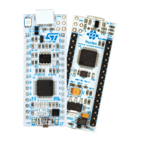
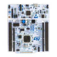
The STM32 Nucleo board is a low-cost and easy-to-use development platform used to
quickly evaluate and start development with an STM32 microcontroller in LQFP64 package.
Before installing and using the product, accept the Evaluation Product License Agreement
from the www.st.com/epla web page.
For more information on the STM32 Nucleo board and to access the demonstration
software, visit www.st.com/stm32nucleo website.
5.1 Getting started
Follow the sequence below to configure the STM32 Nucleo board and launch the demo
software:
1. Check the jumper position on the board, JP1 off, JP5 (PWR) on U5V, JP6 on (IDD),
CN2 on (NUCLEO) selected.
2. For correct identification of all device interfaces from the host PC, install the Nucleo
USB driver available from the www.st.com/stm32nucleo web page, prior to connecting
the board.
3. Connect the STM32 Nucleo board to a PC with a USB cable ‘Type-A to Mini-B’ through
USB connector CN1 to power the board. The red LED LD3 (PWR) and LD1 (COM)
must light up. LD1 (COM) and green LED LD2 must blink.
4. Press button B1 (left button).
5. Observe the blinking frequency of LED LD2 at different frequencies, by clicking on the
button B1.
6. The demonstration software and several software examples on how to use the STM32
Nucleo board features are available at the www.st.com/stm32nucleo web page.
7. Develop the application using the available examples.
5.2 NUCLEO-L476RG bootloader limitations
Boot from system Flash memory results in executing bootloader code stored in the system
Flash memory, protected against write and erase. This allows in-system programming (ISP),
that is, flashing the STM32 user Flash memory. It also allows writing data into RAM. The
data come in via one of the communication interfaces such as USART, SPI, I
2
C bus, USB,
or CAN.
The bootloader version can be identified by reading the bootloader ID at the address
0x1FFF6FFE.
The STM32L476RGT6 part soldered on the NUCLEO-L476RG main board is marked with a
date code, corresponding to its date of manufacturing. STM32L476RGT6 parts with the date
code prior or equal to week 22 of 2015 are fitted with bootloader V
9.0, affected by the
limitations to be worked around, as described hereunder. Parts with the date code starting
from week 23 of 2015 contain bootloader V
9.2 in which the limitations no longer exist.
To locate the visual date code information on the STM32L476RGT6 package, refer to the
section “Package information” of the datasheet (DS10198) available at www.st.com. Date
code related portion of the package marking takes Y
WW format, where Y is the last digit of

 Loading...


