UM2407 Rev 2 31/50
UM2407 Hardware layout and configuration
49
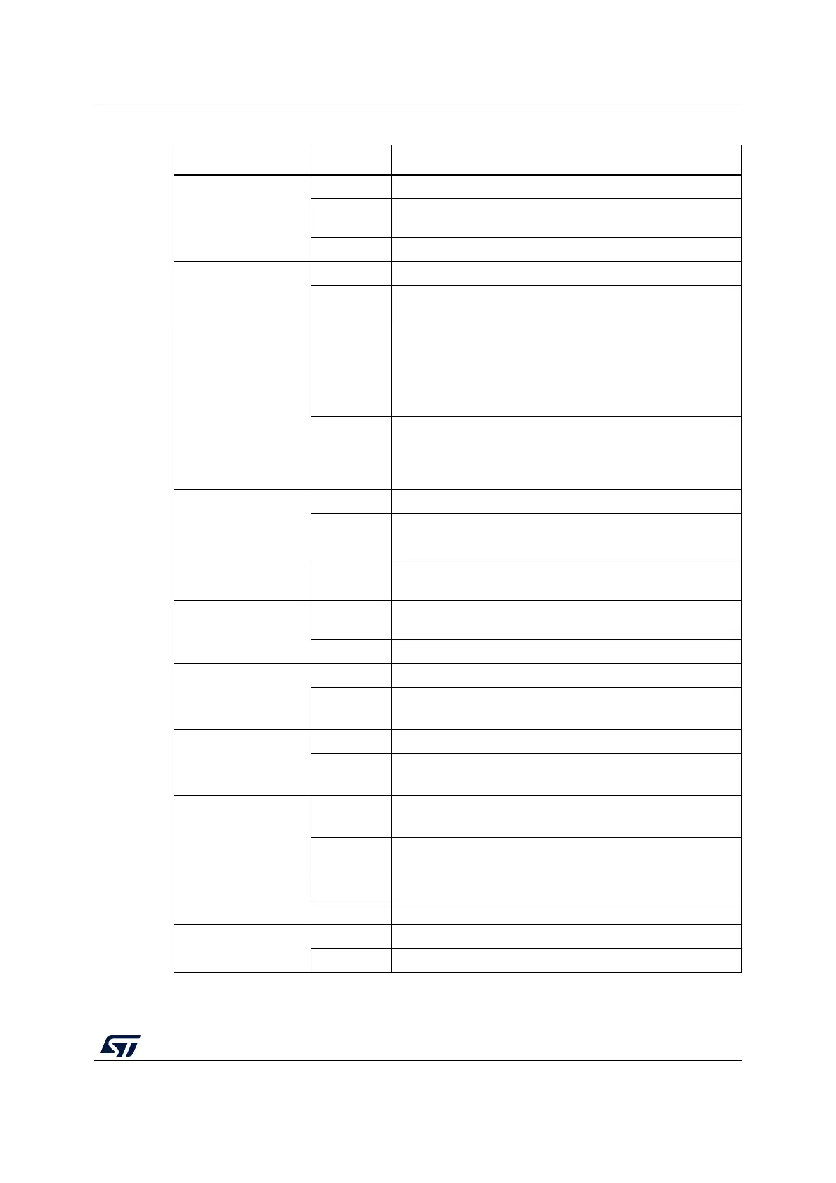
SB51, SB58
(B1-USER)
ON, OFF B1 push-button is connected to PC13.
OFF, ON
B1 push-button is connected to PA0 (Set SB51 OFF if the ST
Zio connector is used).
OFF, OFF B1 push-button is not connected.
SB75
(PA0)
ON PA0 is connected to the ST Zio connector (Pin 29 of CN10).
OFF
PA0 is not connected to the ST Zio connector (Pin 29 of
CN10).
RMII Signals
SB57 (PA1), SB64
(PC1),
SB72 (PA2), SB36
(PC4),
SB29 (PC5), SB30
(PG13), SB27 (PG11),
SB31 (PA7), JP6
(PB13)
ON
These pins are used as RMII signals and connected to
Ethernet PHY.
(SB7 must be removed)
These pins must not be used on the ST morpho or the ST Zio
connectors.
OFF
These pins can be used as GPIOs on the ST morpho
connectors.
PB13 can be used as I2S_A_CK on ST Zio (Pin 5 of CN7) if
not used on the ST morpho.
SB74 (Ethernet nRST)
RMII Signal
ON NRST of STM32H7 is connected to Ethernet PHY (U15).
OFF NRST of STM32H7 is not connected to Ethernet PHY (U15).
SB76 (PG7)
ON USB overcurrent alarm is connected.
OFF
USB overcurrent alarm is not connected. PG7 is used as
GPIO on the ST morpho connector (CN12).
SB77 (PD10)
ON
PD10 is connected to Enable for Power switch (U18) to
control V
BUS
.
OFF PD10 is used as GPIO on the ST morpho connector (CN12).
SB23 (PA9)
ON PA9 is connected to USB V
BUS
.
OFF
PA9 is not connected to USB V
BUS
.
PA9 is used as GPIO on the ST morpho connector (CN12).
SB24 (PA10)
ON PA10 is connected to USB ID.
OFF
PA10 is not connected to USB ID.
PA10 is used as GPIO on the ST morpho connector (CN12).
SB21 (PA11), SB22
(PA12)
ON
These pins are used as D- and D+ on USB connector CN13.
(SB16 and SB17 must be OFF).
OFF
These pins are used as GPIOs on the ST morpho
connectors.
SB13
ON VDD33_USB_1 is connected to 3V3_VDD.
OFF VDD33_USB_1 is not supplied.
SB25
ON VDD_MMC_1 is connected to VDD_MCU.
OFF VDD_MMC_1 is not supplied.
Table 14. Solder bridge and jumper configuration (continued)
Bridge State
(1)
Description

 Loading...


