The related pinout for the USB OTG FS connector is listed in Table 12.
Table 12. CN14 USB OTG FS Micro-AB connector pinout
Connector Pin number Pin name Signal name Function
CN14
1 VBUS USB_FS_VBUS (PA9) 5 V power
2 DM USB_FS_DM (PA11) Data-
3 DP USB_FS_DP (PA12) Data+
4 ID USB_FS_ID (PA10) ID
5 GND - GND
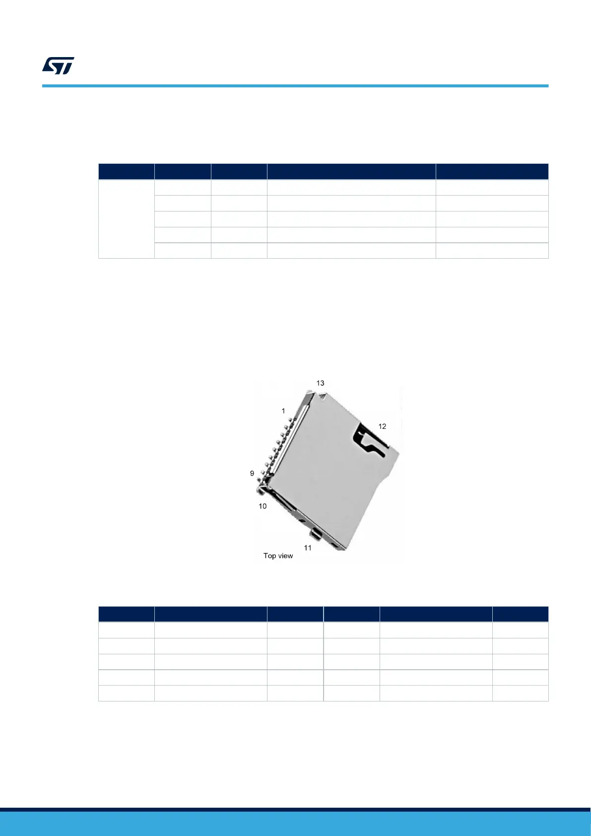
8.3 CN2 microSD™ card connector
microSD
™
cards with 4 GBytes or more capacity can be inserted in the receptacle CN2. Four data bits of the
SDIO1 interface, CLK and CMD signals of the STM32H735IGK6U are used to communicate with the microSD
™
card. The card insertion is detected by the μSD_Detect signal. When a microSD
™
card is inserted, the
μSD_Detect level is LOW, otherwise, it is HIGH.
Figure 12. CN2 microSD
™
card connector
Table 13. CN2 microSD
™
connector pinout
Pin number
Description MCU port Pin number Description MCU port
1 SDIO1_D2 PC10 6-9 GND -
2 SDIO1_D3 PC11 7 SDIO1_D0 PC8
3 SDIO1_CMD PD2 8 SDIO1_D1 PC9
4 VDD (3V3) - 10 μSD_Detect PF5
5 SDIO1_CK PC12 11-12-13-14 GND (casing) -
UM2679
CN2 microSD™ card connector
UM2679 - Rev 1
page 21/42

 Loading...


