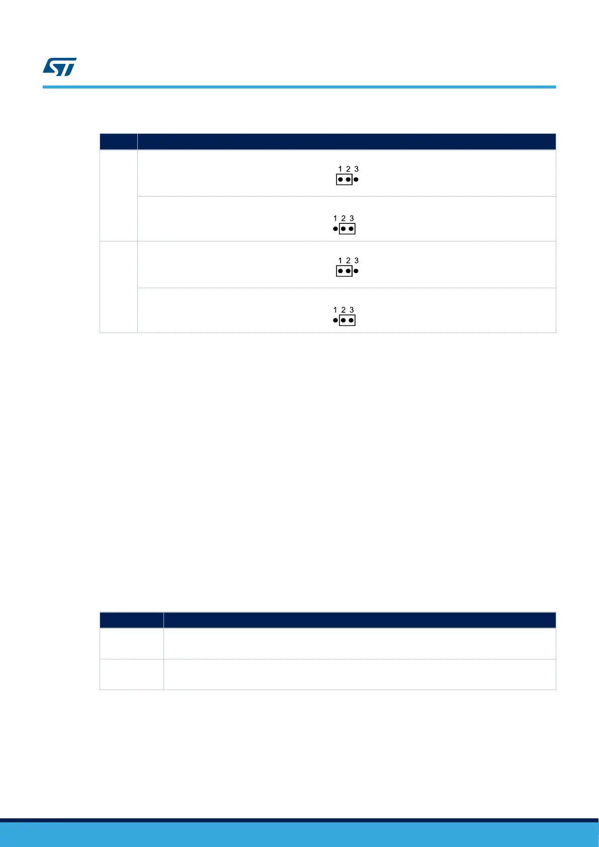
Table 12. USART1 related jumpers
Jumper Description
JP7
USART1_TX is connected to RS232 when JP7 is set as shown below (Default setting):
USART1_TX is connected to the USART_RX of the STLINK-V3E controller when JP7 is set as shown below:
JP8
USART1_RX is connected to RS232 when JP8 is set as shown below (Default setting):
USART1_RX is connected to the USART_TX of the STLINK-V3E controller when JP8 is set as shown below:
6.12
microSD
™
card
The 8-Gbyte (or more) microSD
™
card connected to the SDIO 3.0 port of the STM32H7x7XI microcontroller is
available on the Evaluation board. Detection of the microSD card is managed by MFX GPIO15.
IP4856CX25/C (M1) is an SD 3.0-compliant, 6-bit-bidirectional, dual-voltage-level translator. It is implemented on
the STM32H7x7I-EVAL board and it supports SD 3.0, SDR104, SDR50, DDR50, SDR25, SDR12 and SD 2.0 in
high-speed (50 MHz) and default-speed (25 MHz) modes.
6.13
External I
2
C connector
The I2C1 bus of the STM32H7x7XI is connected to CN4 on the STM32H7x7I-EVAL. The I
2
C functional
daughterboard can be mounted on the CN4 connector and accessed by the microcontroller through the I2C1 bus.
6.14 FDCAN
The STM32H7x7I-EVAL Evaluation board supports one channel of the Flexible Data Rate CAN (FDCAN)
communication bus, based on the 3.3 V CAN transceiver.
The standby signal on the FDCAN transceiver is controlled by PD3 of the STM32H7x7XI. Other FDCAN signals
are shared with USB OTG1_FS signals.
Table 13. CAN related jumpers and solder bridges
Jumper Description
JP1
CAN terminal resistor is enabled when JP1 is ON.
Default setting: OFF
JP2
PA11 is connected with FDCAN RX signal when JP2 is ON.
Default setting: OFF
6.15 Ethernet
The STM32H7x7I-EVAL Evaluation board supports 10M/100M Ethernet communication by a PHY LAN8742A
(U5) and integrated RJ45 connector (CN1). Ethernet PHY is connected to STM32H7x7XI through the RMII
interface.
A 50-M reference clock can be generated by PHY with 25-M crystal or with 25-M MCO from STM32H7x7XI.
These two resources can be selected by setting jumper JP5 as shown in Table 14. Ethernet related jumpers.
UM2525
microSD™ card
UM2525 - Rev 3
page 18/69