6.19 Display and input devices
Four general-purpose-color LEDs (LD 1, 2, 3 and 4) are available as display device.
The 4-direction joystick (B4) with selection, Wakeup (B2) and Tamper/key button (B3) are available as input
devices.
A 4” 800x480 TFT color LCD with capacitive touch panel is connected to the MIPI DSI interface of the
STM32H7x7XI microcontroller.
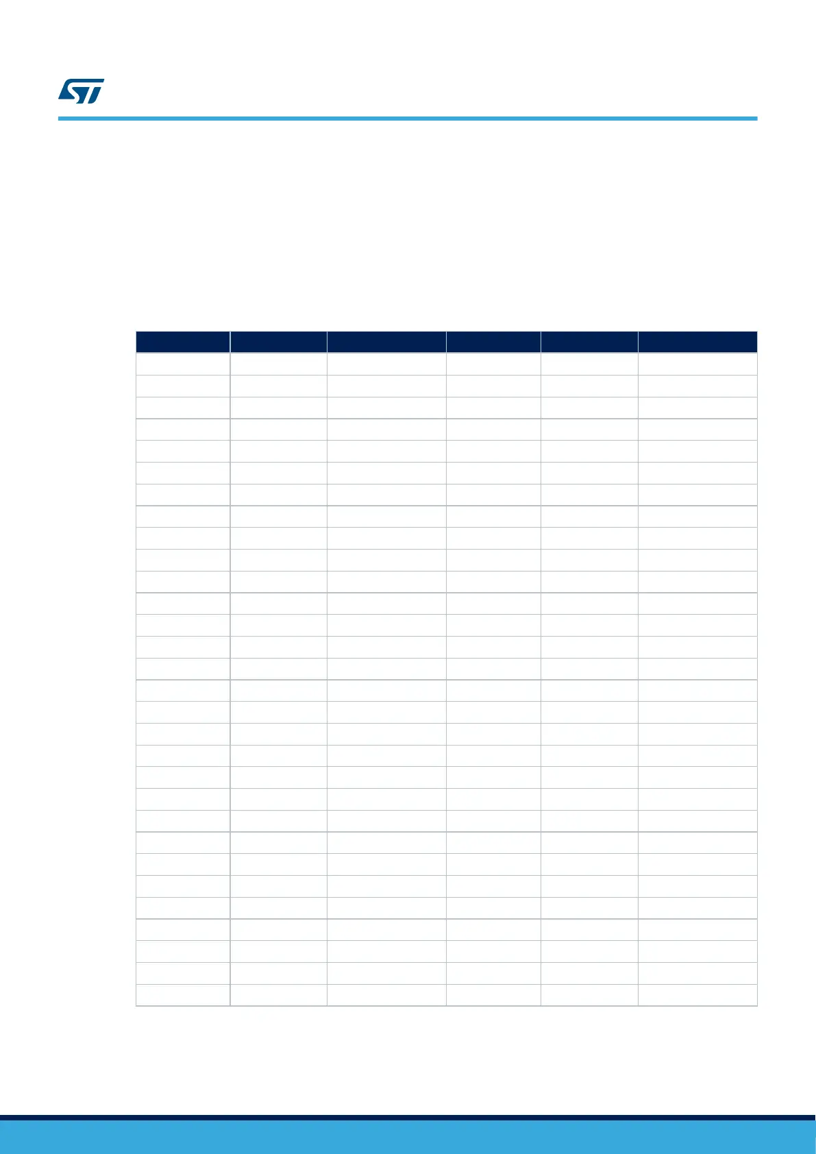
Table 16. LCD module connector (CN15)
Pin number Description Pin connection Pin number Description Pin connection
1 GND - 2 - -
3 DSI_CK_P - 4 TOUCH_INT MFX GPIO14
5 DSI_CK_N - 6 GND -
7 GND - 8 RFU GND
9 DSI_D0_P - 10 RFU GND
11 DSI_D0_N - 12 GND -
13 GND - 14 RFU GND
15 DSI_D1_P - 16 RFU GND
17 DSI_D1_N - 18 GND -
19 GND - 20 - -
21 BLVDD(5V) - 22 - -
23 BLVDD(5V) - 24 - -
25 - - 26 - -
27 BLGND - 28 - -
29 BLGND - 30 - -
31 - - 32 - -
33 - - 34 - -
35 SCLK/MCLK PE5 36 3.3V -
37 LRCLK PE4 38 - -
39 I2S_DATA PE6 40 I2C1_SDA PB7
41 - - 42 -
43 - - 44 I2C1_SCL PB6
45 CEC_CLK PA8 46 - -
47 CEC PA15 48 - -
49 DSI_TE PJ2 50 - -
51 - - 52 - -
53 BL_CTRL PA6 54 - -
55 - 56 - -
57 DSI_RESET PF10 58 - -
59 - 60 1.8V -
UM2525
Display and input devices
UM2525 - Rev 3
page 20/69