4 Hardware description and configuration
4.1 Interconnection details
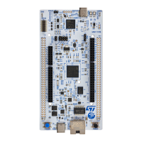
The X-NUCLEO-BNRG2A1 expansion board and the NUCLEO-L476RG development board connection details
are listed in the table below
.
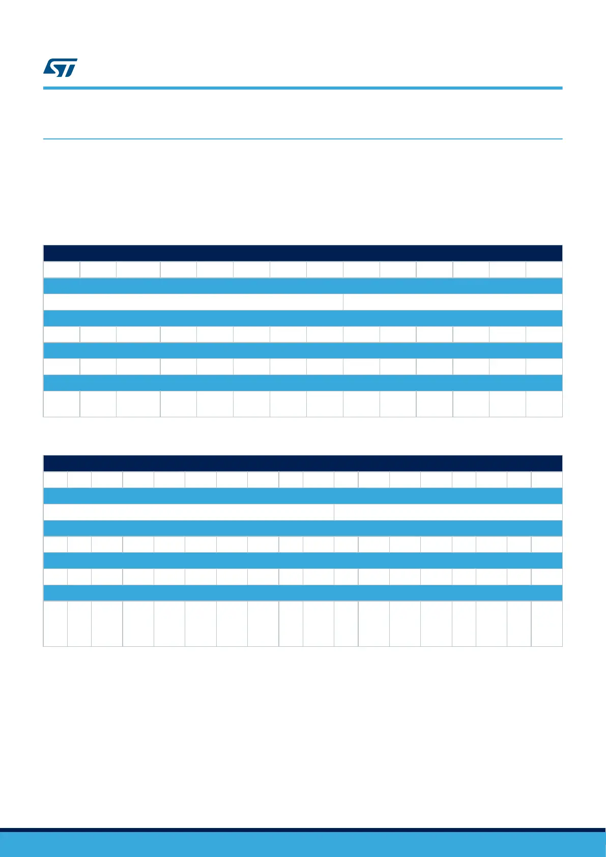
Table 2. X-NUCLEO-BNRG2A1 and NUCLEO-L476RG connection details (left connector)
Signal name
NC IOREF RESET +3V3 +5 V GND GNDS VIN A0 A1 A2 A3 A4 A5
Connector name
CN6 Power CN8 Analog
Pin number
1 2 3 4 5 6 7 8 1 2 3 4 5 6
NUCLEO-L476RG MCU port
PA0 PA1 PA4 PB0 PC1 PC0
X-NUCLEO-BNRG2A1 expansion board signals
NC IOREF RESET +3V3 +5 V GND GND VIN
DIO7/
BOOT
DIO1/
SPI_CS
- - - -
Table 3. X-NUCLEO-BNRG2A1 and NUCLEO-L476RG connection details (right connector)
Signal name
D15 D14 - - D13 D12 D11 D10 D9 D8 D7 D6 D5 D4 D3 D2 D1 D0
Connector name
CN5 Digital CN9 Digital
Pin number
10 9 8 7 6 5 4 3 2 1 8 7 6 5 4 3 2 1
NUCLEO-L476RG MCU port
PB8 PB9 AVDD GND PA5 PA6 PA7 PB6 PC7 PA9 PA8 PB10 PB4 PB5 PB3 PA10 PA2 PA3
X-NUCLEO-BNRG2A1 expansion board signals
- - AREF GND
DIO0/
SPI_C
LK
DIO2 DIO3 - - DIO4 - DIO6 DIO12 DIO14
DIO
0/
SPI_
CLK
DIO5
DIO
1
1/
SPI_
CS
DIO8
Note: To use PA1 as SPI_CS with DIO1 mount resistor R70.
T
o use PA1 as SPI_CS with DIO11 mount resistor R76.
To use PA2 as SPI_CS with DIO11 mount resistor R86.
To take control of RESET in the STM32 application with PA8, mount resistor R117.
4.2 SPI and GPIO connection options
The SPI and GPIO connection options between the STM32 Nucleo and BlueNRG-M2 on the X-NUCLEO-
BNRG2A1
expansion board can be used to enable different configurations in case a signal conflict occurs when
using other expansion boards.
UM2667
Hardware description and configuration
UM2667 - Rev 1
page 6/22

 Loading...