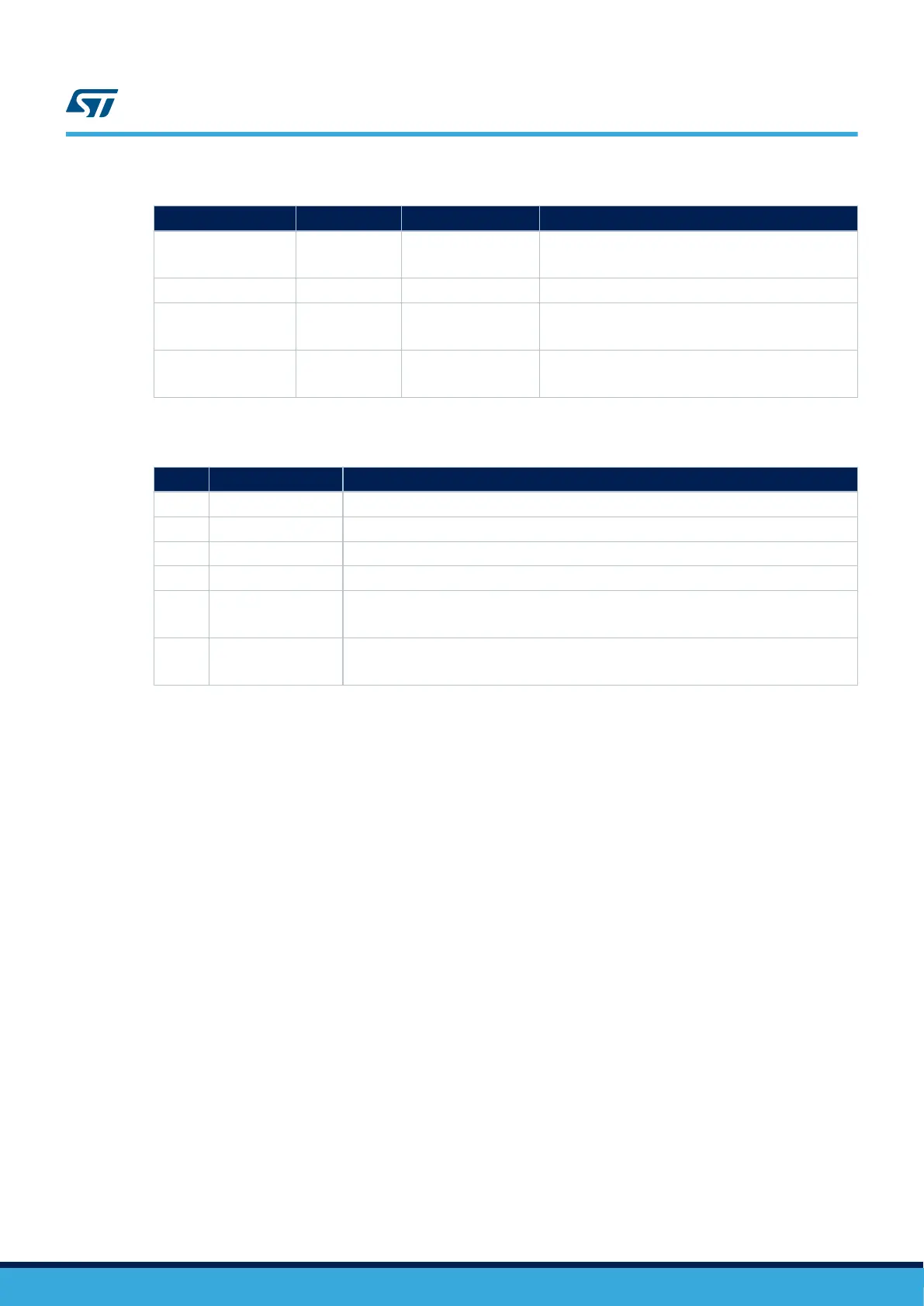
Table 4. X-NUCLEO-BNRG2A1 interface with STM32 Nucleo development board
X-NUCLEO-BNRG2A1 BlueNRG-M2SP Default STM32 port Optional STM32 port
PA0_SPI_IRQ_PB14
_BNRG1BOOT
DIO7/BOOT PA0
PB14
T
o use the optional port, mount R82 and unmount R85
DIO1_SPI_CS DIO1 PA1 -
DIO11_SPI_CS DIO11 PA1
PA2
T
o use the optional port, mount R86 and unmount R76
SPI_CLK DIO0
PA5
JP14: pins 1-2 shorted
PB3
T
o use the optional port, short J14 pins 2 and 3
Table 5. X-NUCLEO-BNRG2A1 jumpers
Jumper Signals Description
J10 3.3 V Power connector
J11 User application
J12 SWD For SWD debugging/programming
J13 User application
J14 SPI_CLK
To select the SPI clock pin PA5 or PB3
Default: pins 1-2 shorted
J15
PA0_SPI_IRQ
_PB14_BNRG1BOOT
This jumper is connected to DIO7 of the BlueNRG-2 and must be shorted for boot pin high.
DIO7 can be used for Bootloader activation.
4.3 Current measurement
To monitor the X-NUCLEO-BNRG2A1 expansion board power consumption, insert an ammeter probe between
pin 1 and 2 of the jumper J10 connector.
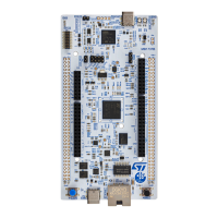
4.4 X-NUCLEO-BNRG2A1 component placement details
The figure below shows the component placement on the X-NUCLEO-BNRG2A1 expansion board.
UM2667
Current measurement
UM2667 - Rev 1
page 7/22

 Loading...