– 4 –
LED1
LED2
SW2
3. Since it is adjusted by rotating the volume VR6, check the position of the volume. Prepare a small slotted
screwdriver.
4. Set the roll paper.
5. Use the tip of a thin object to turn off the DIP switch DSW 1-4.
6. Press the SW2 switch on the control panel while turning the power switch ON.
7. Rotate the volume VR6 using micro screwdriver, to adjust it to a position whereat both the LED1(green LED) and
the LED2 (red LED) lamps light.
8. When the position where both LEDs for LED1/LED2 light cannnot be found by adjusting VR6, Adjust VR6 to the
position where the LED2 lights and LED1 extinguishes.
9. Turn the power OFF.
10
. Turn the DIP switch DSW1-4 to its original setting of ON.
This completes the paper near end sensor adjustment.
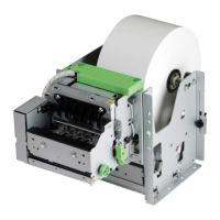
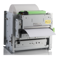
Fig. 1-4 Control Panel
 Loading...