41 | P a g e
8 Digital Inputs And Outputs
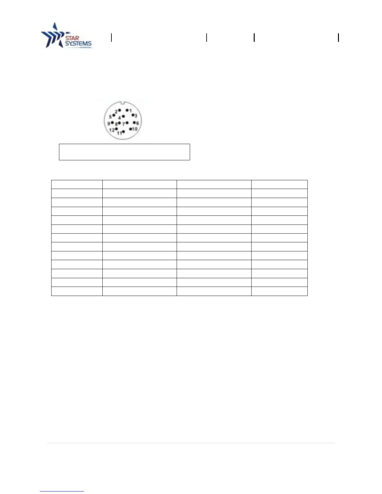
Digital input and output signals are provided via the bulkhead connectors. Refer to the following
diagram specifications for the connector pin out:
8.1 Digital Inputs
There are 2 isolated digital input channels that may be used as general purpose inputs or to trigger
the reader for tag reading. By default, the digital inputs are set to an open state. To activate the input,
connect the reader’s digital input to a relay. When the relay is closed, the connected digital input will
be closed. No voltage higher than +5 Vdc or lower than 0 Vdc should ever be connected to the input
channels with maximum current at 500mA.
8.2 Digital Outputs
There are 2 isolated digital output channels that may be used as general purpose outputs, to indicate
tag reading activity, or to indicate the reader is transmitting (RF On). Digital outputs can be pulled
high and close the internal relay. Any external circuits that connect to the digital output shall not be
higher than 120VAC with maximum current at 0.5A, or 24VDC with maximum current at 1A.