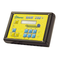
MANUFACTURER menu
13
[SPD SENS] Pressing _>_ takes you to a sub-menu with the following options relating to the SPEED SEnsor
attached to the irrigator: ROLLEr or PINIon.
[SS ROLLE]
[SS PINI]
Pressing _>_ takes you to a sub-menu with the following option:
[SSR 1OO.O]
this parameter lets you input the diameter of the
Roller. This dimension is expressed in millimetres
with increments of 1/10 mm.
[TAB LAYE] TABle of LAYErs (applies only to the sensor mounted on the pinion).
Pressing _>_ takes you to the Table of Layers with the following options
(the data in this table are all modifiable and can be scrolled upwards or
downwards):
[LL1 448.4]
this figure indicates at what Length Layer 1 finishes.
Pressing _>_ takes you to another datum figure.
[PL1 16.O]
indicates the Parameter of
Layer 1, mm/imp.
[LL2 388.5]
this figure indicates at what Length Layer 2 finishes.
Pressing _>_ takes you to another datum figure.
[PL2 19.O]
indicates the Parameter of
Layer 2, mm/imp
[LLX 320.3]
this figure indicates at what Length Layer X
finishes.
Pressing _>_ takes you to another datum figure.
[PLX 22.O]
indicates the Parameter of
Layer X, mm/imp
[LL9 O.O]
this figure indicates at what Length Layer 9 finishes.
Pressing _>_ takes you to another datum figure.
[PL9 36.O]
indicates the Parameter of
Layer 9, mm/imp
[AUTO CAL] AUTOmatic CALculation of the table of layers (applies only to the sensor
mounted on the pinion). Pressing _>_ takes you to the parameters for the
construction data of the irrigator. By suitably filling in the items listed below,
you can get the table of layers filled in automatically:
[LPI 5OO.O]
this figure indicates the Length of the PIpe.
Expressed in metres. Maximum length 1000 m
[DPIP 14O] this figure indicates the Diameter of the PIPe.
Expressed in millimetres. Maximum diameter 200
mm
[DRE 154O] this figure indicates the Diameter of the REel.
Expressed in millimetres. Maximum diameter 2000
mm.
[WRE 1536] this figure indicates the Width of the REel.
Expressed in millimetres. Maximum width 2000 mm
[PULR 32O] this figure indicates the number of PULses per
Revolution. Normally this is equal to the number of
teeth on the rack. Maximum number 400.
[K1 S 2%] this figure indicates the percentage deformation of
the pipe (Stretching). Maximum permissible 20%.
[K2 C 4%] this figure indicates the percentage deformation of
the pipe (Crushing). Maximum permissible 20%.
[K3 F 0%] this figure indicates the percentage difference
between the First coil and the last. Maximum
permissible 20%. (not active)
[CALC?TAB] CALCulating the TABle.. Pressing _ENTER _
gives you [CALTB*OK]
[CALTB*OK] It displays the calculation which has been done and
the table filled in with the new parameters.
Press the _<_ cursor key to exit the automatic table
calculator function.

 Loading...