EasyManua.ls Logo

Steca TR 0704 - Page 44

Steca TR 0704
84 pages
Print Icon
To Next Page IconTo Next Page
To Previous Page IconTo Previous Page
Loading...
44
To prevent erroneous settings, the described switch-on and switch-off values are interlocked,
this means they can be set only at a specific value to one other.
Since with this diagram, speed controls are only useful when the objective is "absolute
temperature", this control objective has been saved both in the settings "Absolute temp." and
also "Differential temp.". The control devices are therefore dependent on this setting.
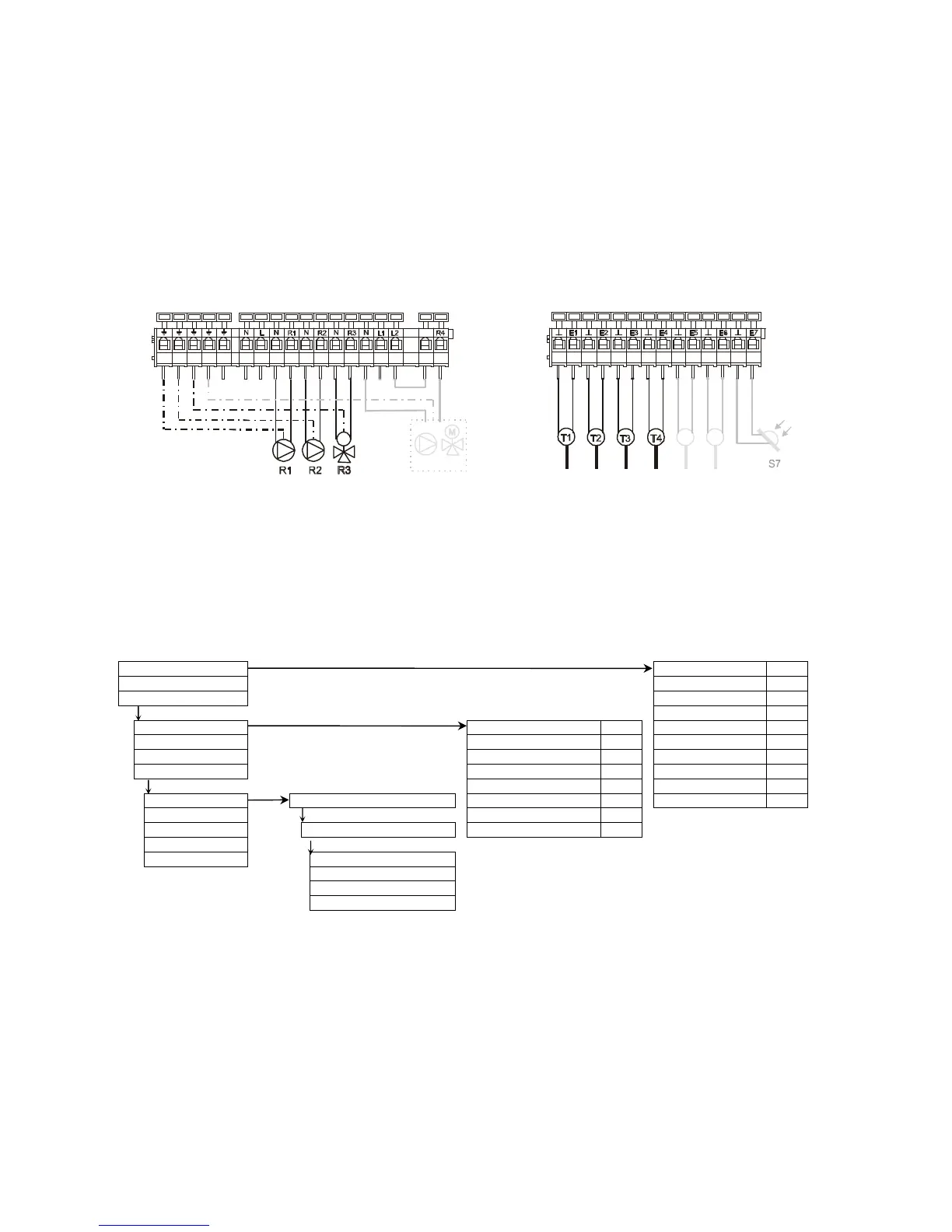
Connecting diagram:
Menu navigation: (here for the scheme 'Basic' )
OK
Measuring values
collector: °C
Operating status
storage 1 bottom: °C
+Settings
storage 2 bottom: °C
OK OK
charging temp. °C
Parameter
storage 1 max. 70°C
char
g
e-
um
Δ:
h
Date / Time
storage 2 max. 70°C
char
g
e-
um
Σ:
h
+Clocks
collector max.
130°
sola
r
-
um
Δ:
h
+Service
Diff. temp. solar ON 8K
sola
r
-
p
um
p
Σ:
h
OK OK + Menu (2 sec.)
Diff. temp. solar OFF 4K
reversin
g
valve Δ:
h
System selection -plate heat exchanger
charging temp. max.
115°
reversin
g
valve Σ:
h
Functions
OK
charging setpoint 65°C
Links
+2 storage tanks AH extern. threshold 0°C
Extras
OK
Manual operation ~Basic
choose with OK (2sec.)
{Basic-CZ
{Basic-AH
{Basic-R
M
T5
R4 R4
T6

Related product manuals