45
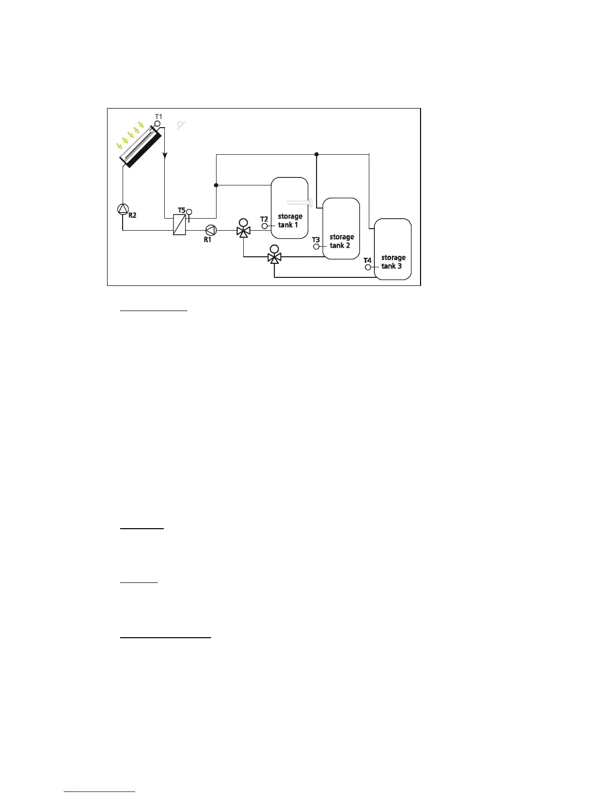
4.2.3 Plate heat exchanger, 3 storage tanks
If, in the 'System
selection’'
menu, the points "Plate
heat exchanger", "3
storage tanks" and
"Basic" are selected, the
hydraulic diagram
illustrated here is
available for use as a
basic system (basic) with
the indicated variants.
• "Basic" system:
The regulator constantly records the differential temperature between the sensors
T1 and T2, T1 and T3 or T1 and T4. If the set switch-on differential temperature (parameter: 'diff.
temp. solar ON') is reached, the solar circuit pump R2 switches on and heats the solar circuit with
the plate heat exchanger. The R2 speed control regulates the temperature of the solar flow
(advance) (T1) to the "Required loading temp." value + 5 Kelvin. If the temperature level on the
plate heat exchanger T5 reaches a value of at least 5 Kelvin more than the 'Lower part of storage
tank x’ temperature T2, T3 or T4 and if T5 is at least 3K above the parameter value “AH extern.
threshold “ the charging requirements are met for storage tank 1 (charging below this value could
otherwise lead to the unintentional activation of any installed external after-heating), R1 switches
on with minimum speed and then regulates the temperature of the charging current at the
corresponding required value (parameter: ‘charging setpoint x'). This happens until either the
maximum storing temperature (parameter: ''storage tank x max.') is reached or the differential
temperature between T5 and T2, T5 and T3 or T5 and T4 falls below a value of 3 Kelvin. The solar
circuit pump R2 remains active until either the maximum storing temperature (parameter: ''storage
tank x max.') is reached or below the switch-off differential temperature of the solar circuit
(parameter: 'diff. temp. solar OFF'). To protect the charging circuit from overheating, the solar
circuit is deactivated when T5 is only 3 Kelvin below the maximum charging temperature
(parameter: 'Max. charging temp. x'). If the charging circuit continues to heat up because of an
erroneous function, R1 is also deactivated when the maximum charging temperature is reached.
Definition
: Storage tank 1 is charged when the 3-way valves (R3, R4) are in a de-energized
state!
Storage tank 2 is charged when the 3-way valve R4 is in a de-energized state (R3
energized)!
Warning:
The parameter value “AH extern. threshold” is factory set to 0°C. This corresponds with
the setting when no external after-heating is connected. If external after-heating system (e.g.
heating cartridge) must be installed in your system, the parameter “AH extern. threshold” must be
set accordingly.
• "Basic - R" diagram:
In some cases the solar circuit pump must be controlled according to the
solar radiation. For this reason, a S7 radiation sensor must be installed in the collector level. For
control purposes T1 must be inserted between the collector and bypass. A detailed functional
description of this add-on can be found on page 15.
To prevent erroneous settings, the described switch-on and switch-off values are interlocked,
this means they can be set only at a specific value to one other.
or S7 (radiation sensor) for Basic-R
M
R3
M
R4
if so with
external
after-heating