Chuck the 3D print tool into the spindle. Lock the 3D print head into the tensioning system with an Allen key.
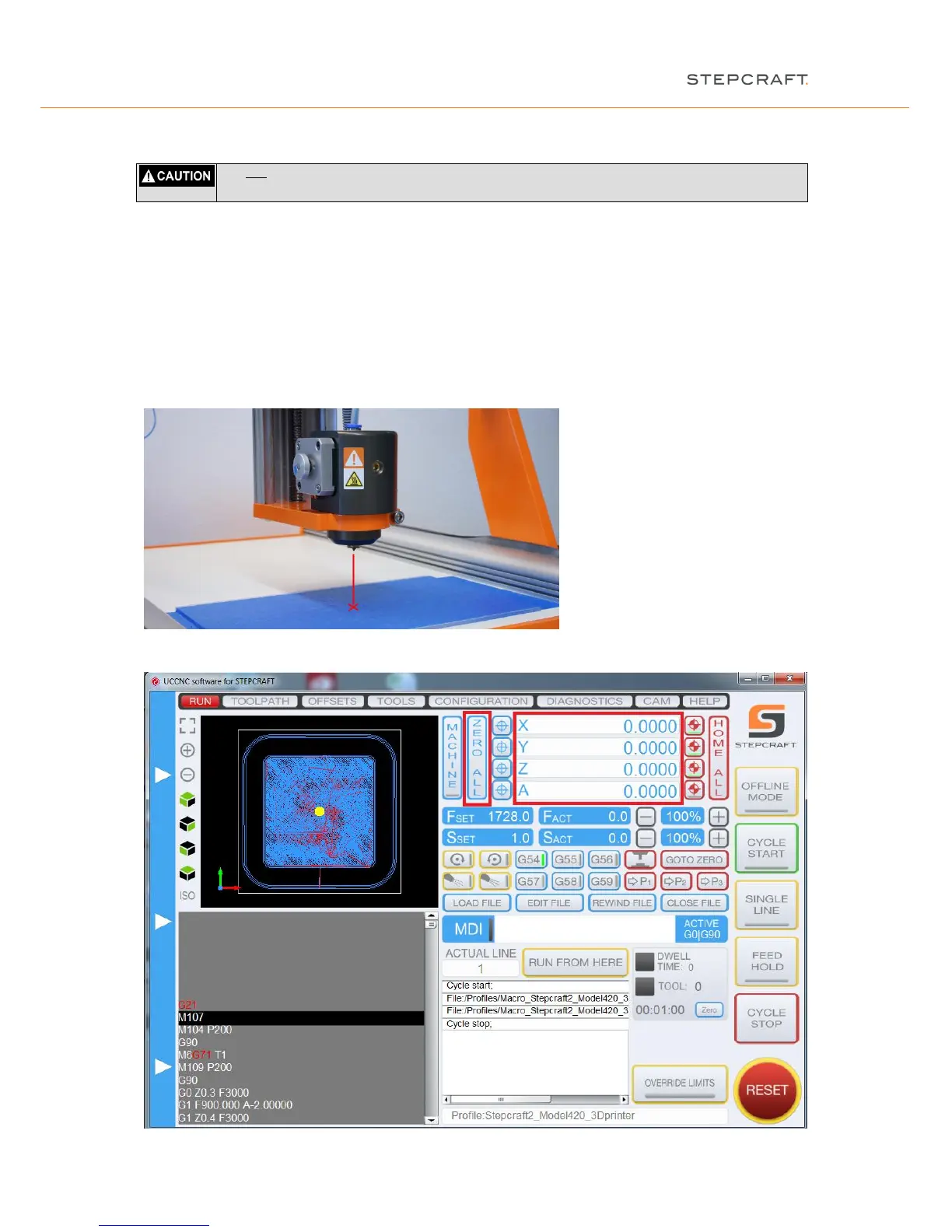
Beside the knowledge of the starting point of the CNC code you need to define the starting point on the work
sheet. This point is also called workpiece zero point. Highlight this point with an "X". Make sure that, when seen
from the front, there is sufficient travel available to the left and right and to the front and rear side (at least 40 -
50 mm in each direction).
Open the "jog" menu by moving your mouse pointer about the left screen side of the program and then drive the
machine manually to the point marked. Move the Z-axis to half maximum height.
Alternatively you can also use the cursor keys (left, right, top, down, picture up / down) of the keyboard to jog the
gantry.
Save these settings by clicking "Zero all" in the main screen.
 Loading...