®
3 Components and functions
© F. Stephan GmbH SA-112-0106V1.0-WEM-GB 21
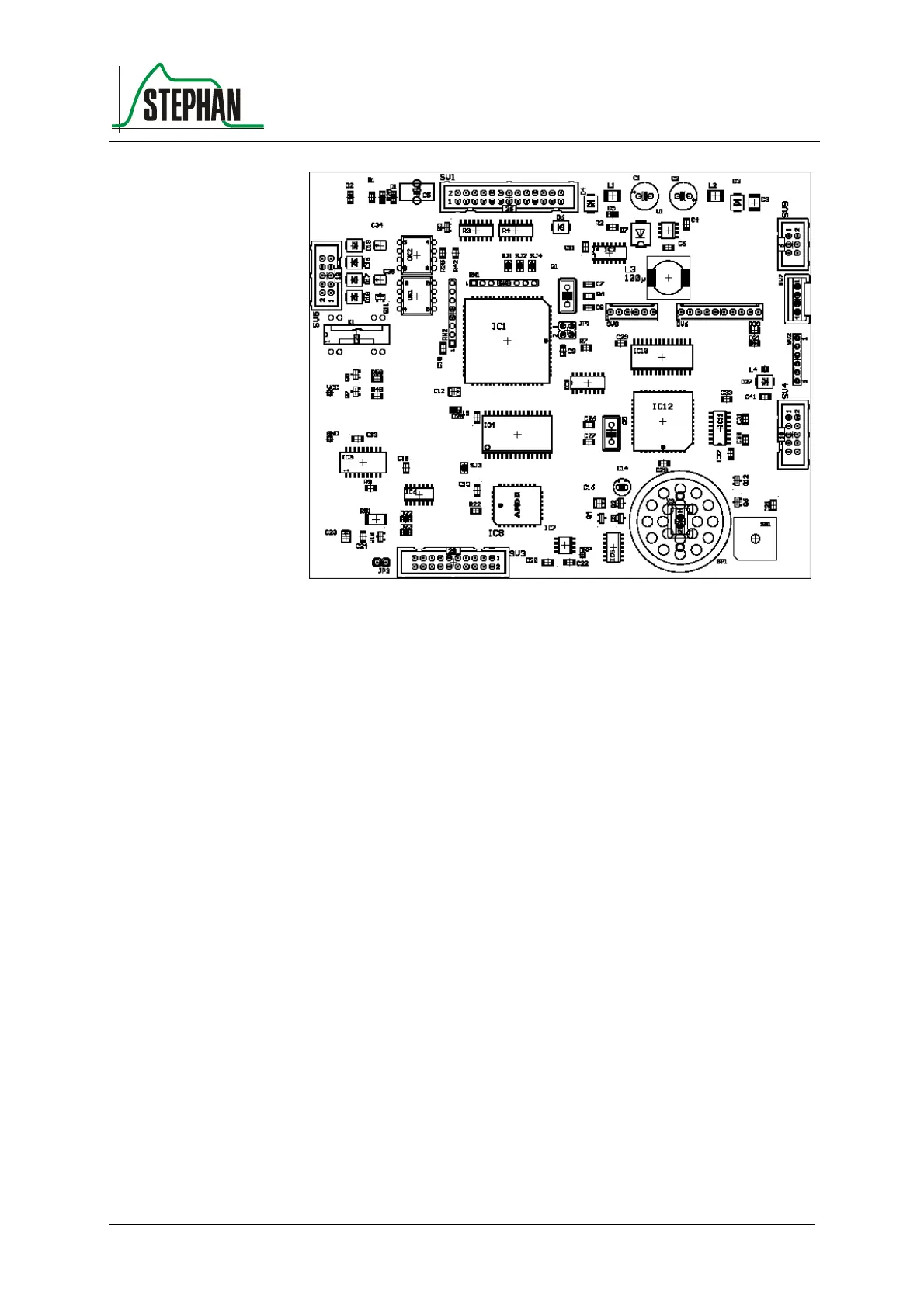
Fig. 14: Controller board
The main task of the controller board is to proceed with ventilation.
The procedure consists of registering the measured values of the sensor
board and calculating the values for output.
If the monitor fails, the limit values are still monitored and acoustic
alarms are produced if necessary.
The processor is an M68HC11 with external Flash ROM and RAM. The
necessary voltage of +5V is generated on the board itself (switching
regulator).
Two acoustic alarms are generated (piezo electric signal transducer,
loudspeaker) and two visual alarms.
An RS232 converter with optocoupler for electrical isolation is used for
communication with a PC.
The second RS232 converter without electrical isolation is not used on
this board.
A further task performed by the controller board is to manage the GUI
(graphical user interface).
The signals of the capacitive sensor button on the front panel and of the
incremental transducer (IGR) are read and processed by processor
M68HC11.
In addition, the graphic output is generated on the LCD.
Main tas