3 Components and functions
24 SA-112-0106V1.0-WEM-GB © F. Stephan GmbH
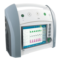
Fig. 17: Battery display
Once the ON switch on the front of the unit has been pressed, the system
starts with a self-test which shows the user that the control elements are
functioning. The self-test consists of the following sequence:
1. green LED of the mains power supply lights up
2. green LED of the 12V vehicle power supply lights up
3. green LED of the battery lights up
4. red LED of the battery lights up
5. piezo sounds
6. everything goes off again
The battery test is only carried out when A
LIA starts up.
The supply voltages are switched off internally for this purpose.
The test is displayed by the red and green LEDs in the battery symbol
which flash alternately.
The battery test is carried out with load on the battery by switching the
compressor on (approx. 2 amps for 6 s). This starts immediately after the
self-test. A brief alarm is given if the system does not pass the battery
test.
Total discharge protection comes into force when the measured voltage
of the battery is <10.8V ( Batt_enable = 0). An acoustic and visual alarm
is given.
The user should stop using the ventilator and recharge the battery, or
provide another voltage source.
The compressor is switched on/off without any contact.
Testing the LEDs and
the piezo
Battery test
Total discharge
protection for the
battery
Compressor ON/OFF