18
13406 SE 32nd St, BELLEVUE WA, 98005 WWW.CONSUMER.STEPPIR.COM TEL: (425)-453-1910
Determining the Direction of the Antenna
The SteppIR Yagi has three “directions” in which it can be used. Normal, 180 degree and Bi-
directional. When the antenna is installed on its mast the passive element should be facing the
direction the rotator indicates. Keep this in mind for when you install the antenna onto the mast
at the end of the antenna assembly.
• In the Normal mode the antenna directs RF energy towards the passive element (the ele-
ment that does not have the coax attached to it), giving gain in that direction and rejecting
signals coming directly at the driven element from the opposite direction.
• In the 180° mode the gain is now directed from the driven element end and rejected from the
passive end.
• In the Bi-Directional mode, your antenna is directing RF in both directions.
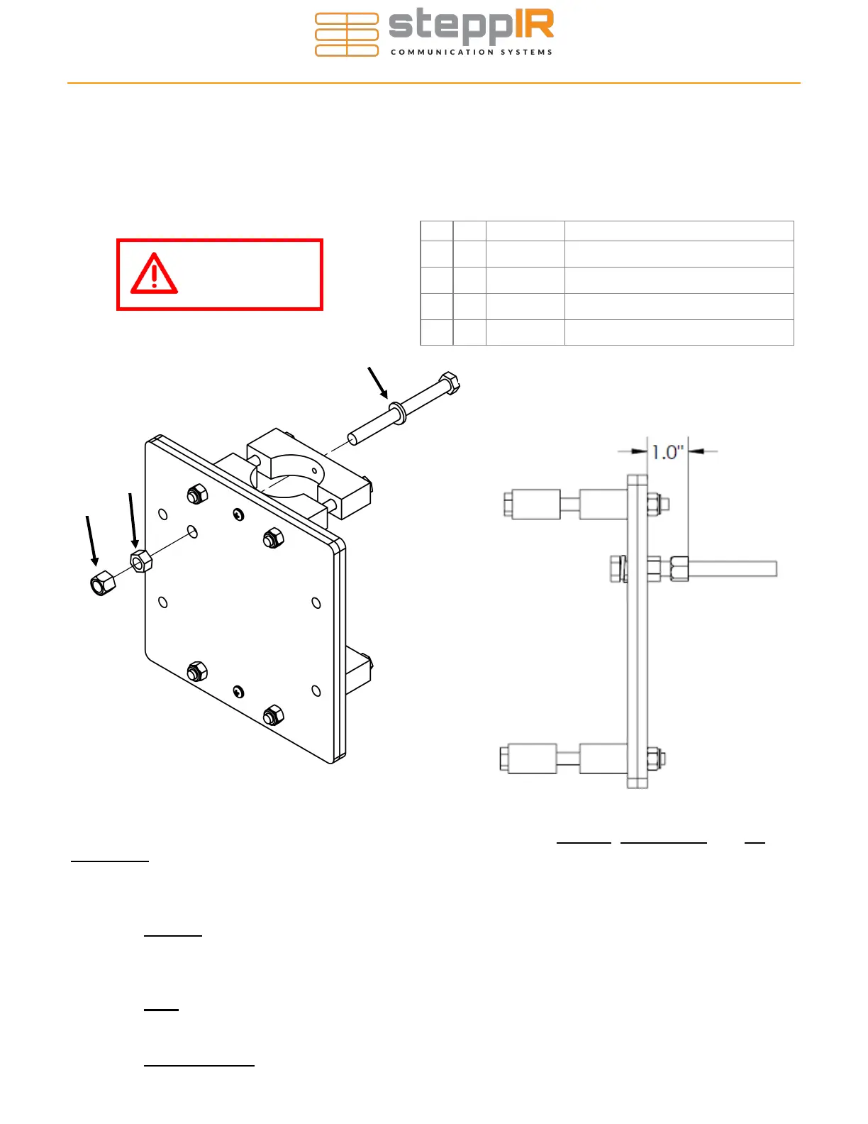
CONNECTING THE MAST PLATE TO THE BOOM
Section 2.2: Install the Fully Threaded Bolt
• Tighten 3/8” nut (C) first.
• When installing the 3/8” Nylock Nut (D), thread it fully with the nylon facing AWAY from the
mast plate first, then take it off and thread it back onto the bolt with the nylon facing TO-
WARD the mast plate.
• The flat face of the Nylock nut should be about 1” from the edge of the mast plate as shown
in Figure 2.22.
Key Qty Part # Description
A 1 60-0085 Hex Bolt, 3/8” x 4”, Fully Threaded
B 1 60-0051 Lock Washer, 3/8”, Split
C 1 60-0049 Nut, 3/8”
D 1 60-0050 Nylock Nut, 3/8”
Use anti-seize on
all stainless
hardware!
A
B
C
D
Figure 2.21
Figure 2.22