19
13406 SE 32nd St, BELLEVUE WA, 98005 WWW.CONSUMER.STEPPIR.COM TEL: (425)-453-1910
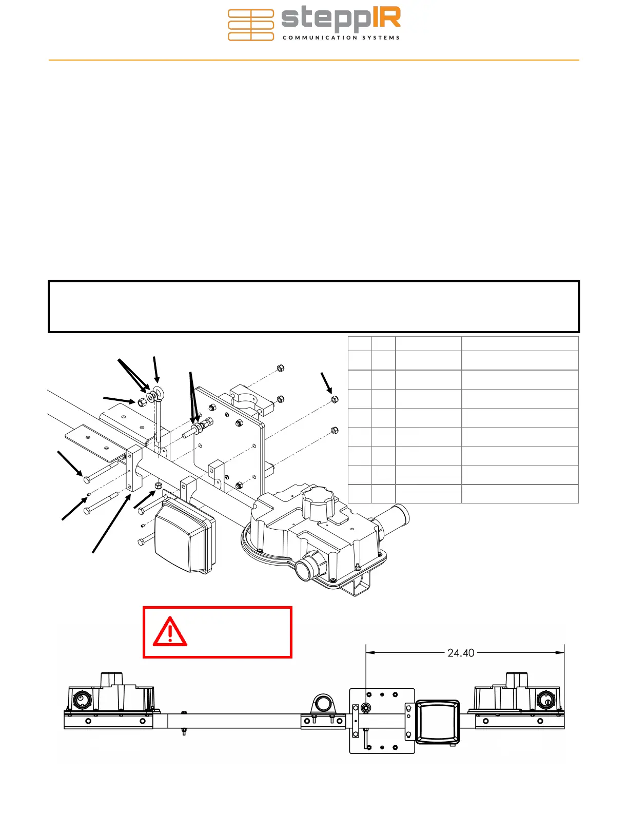
CONNECTING THE MAST PLATE TO THE BOOM
Section 2.3: Install the High Wind Kit
• Position the high wind kit using the Figure 2.31 as reference.
• Mark a hole on the top of the boom directly under the eyebolt stud, 24.40” from the bracket of the Di-
rector EHU as shown in Figure 2.32.
• Place the boom on a flat level surface with the element mounting brackets facing up and leveled.
• Make sure the mark is on the top center of the boom.
• Center punch the mark.
• Drill straight down through both sides of the boom with the provided 5/16” (.3125”) drill bit.
• Use the exploded view drawing below to install the mast plate. Discard the included washer and non-
Nylock nut on the Eyebolt, it will not be used.
• Adjust the two Nylock nuts on the EZ-Eye stud to make sure the boom is level (mast plate perpendic-
ular to element plates).
• Tighten the Nylock nuts first, then set screws on the boom saddle clamps and Nylock nuts on the EZ-
Eye.
C
B
D
E
A
F
G
C
F
Director
Figure 2.31
H
Key Qty Part # Description
A 4 10-1601-03 Saddle, 1-3/4” x 3/4”
B 4 60-0065 Hex Bolt, 5/16” x 3-1/2”
C 5 60-0046 Nylock Nut, 5/16”
D 2 60-0112 Set Screw, 10-32 x 1/4”
E 1 60-0037-21 Eyebolt, 5/16" x 4"
F 4 60-0034 Washer, 3/8”
G 1 60-0050 Nylock Nut, 3/8”
H 1 70-2034 Connector Junction Box
NOTE: The boom can be re-leveled if necessary by loosening the bolts on the boom saddle
clamps and then adjusting the two Nylock nuts that position the EZ-Eye. Be sure to tighten all
nuts when finished.
Director
Driven
Use anti-seize on
all stainless
hardware!
Although the EHUs are shown in
the diagram, they should not be
mounted to the boom yet—they are
here for reference.
Figure 2.32