20
13406 SE 32nd St, BELLEVUE WA, 98005 WWW.CONSUMER.STEPPIR.COM TEL: (425)-453-1910
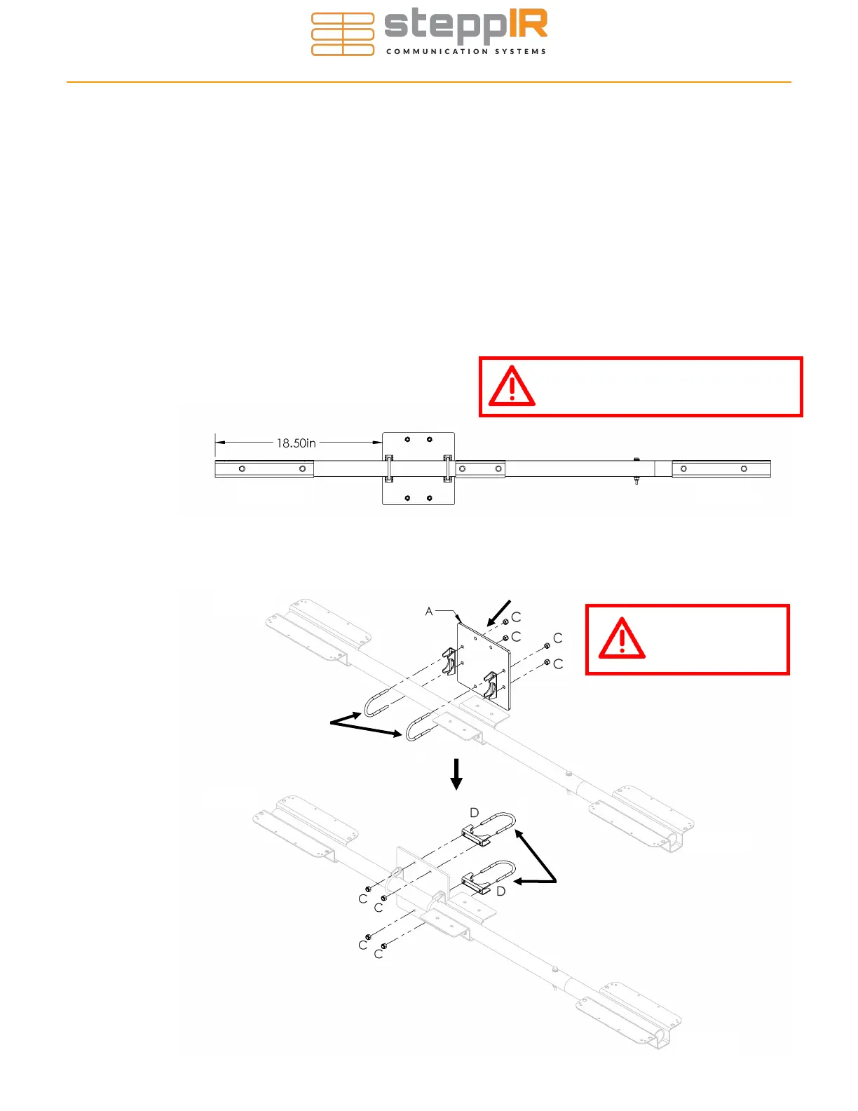
Figure 2.41
Driven
Director
CONNECTING THE MAST PLATE TO THE BOOM
Section 2.4: Install the Mast Plate (No High Wind Kit, Old Version)
Skip if you have the high wind kit
The older version of the mast plate has 8 pre-drilled holes. Four holes are used for the 2” stain-
less steel mast clamps (D) and four more holes are used for the 1-3/4” stainless steel boom
clamps (B).
Connect the boom to the mounting plate (Figure 2.42), using the 1-3/4” U-bolts, saddles, and
nuts. Align the boom so that the element brackets are level (mast plate is perpendicular to ele-
ment brackets), then tighten securely. Ensure the mounting plate is the correct distance from the
director element plate (18.50” from end of bracket) as shown in Figure 2.41.
Connect the mast to the mast plate (once antenna is completely assembled) using the included
2” stainless steel U-bolts, with saddles, and Nylock nuts as shown in Figure 2.42. Tighten se-
curely.
With this mounting style, it doesn’t matter which side
of the boom the mast plate goes on—that’s up to you.
View orientation changed to more
clearly show the assembly!
Figure 2.42
Driven
Director
Director
Driven
Junction Box slots on to left U-Bolt (B)
and is secured with the nuts (C) on the
back side of this mast plate.
Use anti-seize on
all stainless
hardware!
B
B
1.75” SS U-bolts/
saddles for Boom
2” SS U-bolts/
saddles for Boom