39
13406 SE 32nd St, BELLEVUE WA, 98005 WWW.CONSUMER.STEPPIR.COM TEL: (425)-453-1910
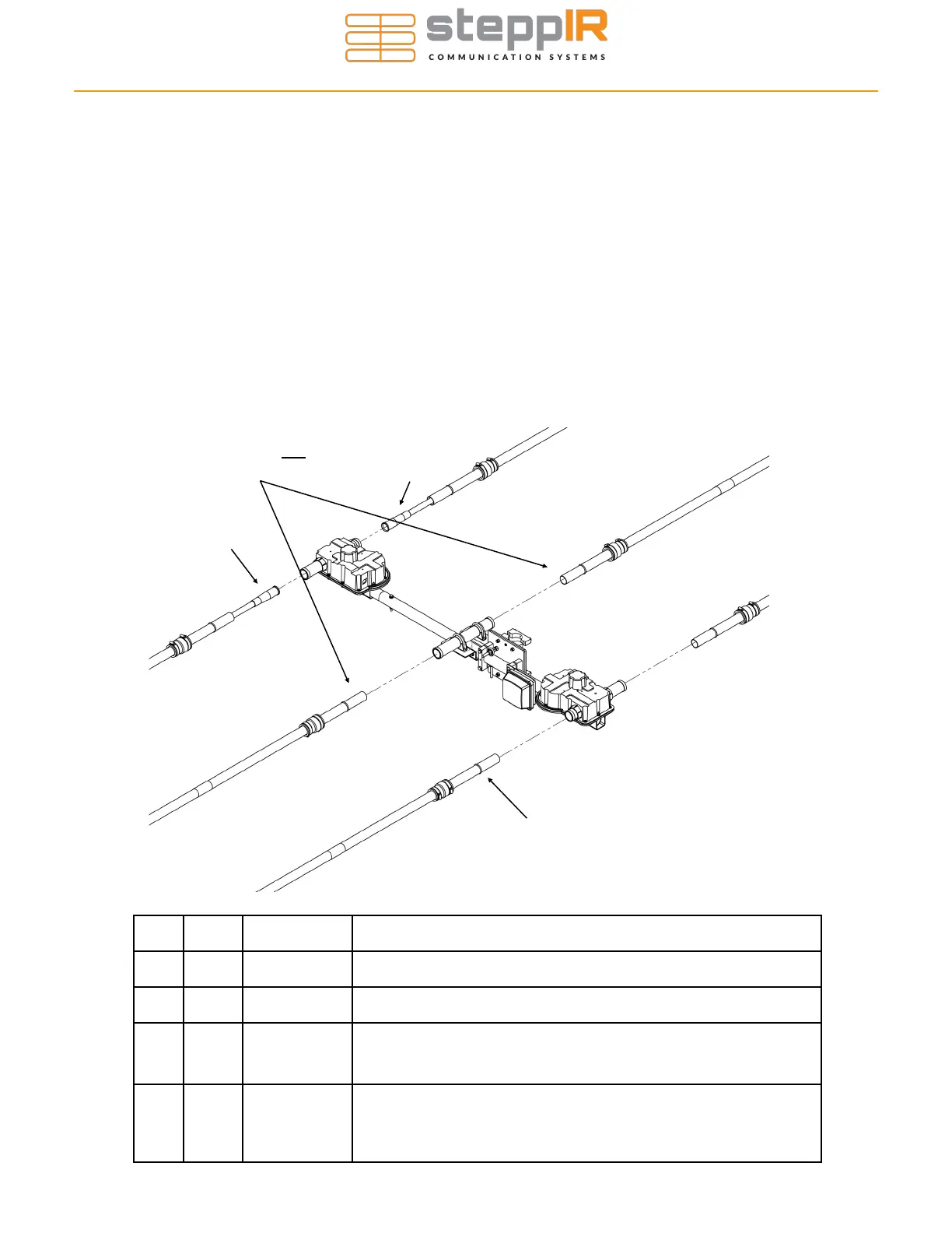
Section 7.2: Securing the Telescoping Poles to the EHUs
When the CPVC inner guide tubes are completed, they will need to be inserted into the tele-
scoping poles and secured to each EHU. Figure 7.21 below gives an overview of this proce-
dure, with detailed instructions following on the next page.
This drawing shows the EHU placement for the driven and director element. The parts required
in the table below are shown for the 40m-6m version of this antenna.
If you have the 20m-6m version of the antenna with no 40/30 loop, the Driven side will match
the Director. The guide tube assemblies, labeled C in Figure 7.21 below, will not be present.
Key QTY Part # Description
A 6 10-1006-22 Quick disconnect boot
B 6 10-1013-02 Telescoping pole
C 2 NA Inner guide tube assembly consisting of diverter cone , 39-7/8”
and 49” CPVC Plastic tube, glued together. They are only used
on the EHU side of the 40/30 loop
D 4 NA Quick disconnect boot locking ring (these are molded into the
base section of each telescoping pole and are used to keep the
pole from sliding out of the quick disconnect boots in high wind
situations)
ATTACHING ELEMENTS TO THE EHUS
A
A
A
A
C
Inner guide tube not required for
the return side of the 40/30 loop
C
D
Figure 7.21
B
A
A
B
B
B
B
Driven
Director