40
13406 SE 32nd St, BELLEVUE WA, 98005 WWW.CONSUMER.STEPPIR.COM TEL: (425)-453-1910
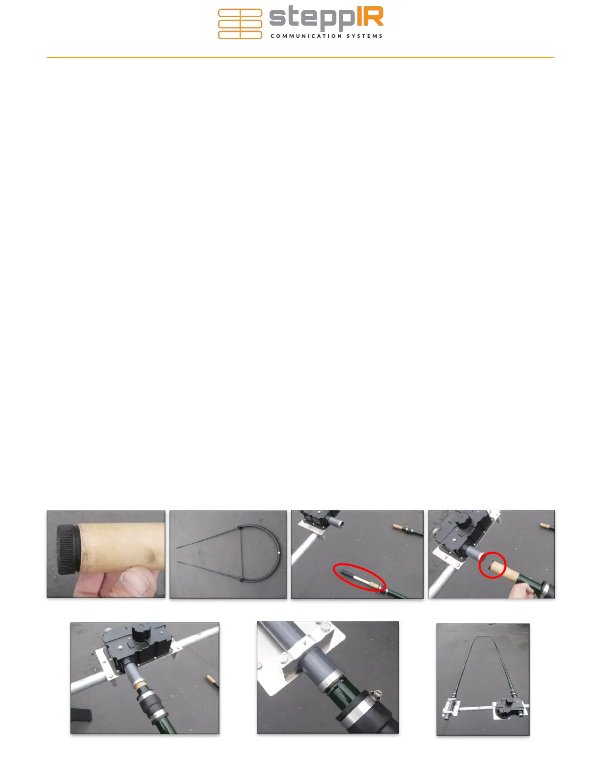
When attaching the telescoping fiberglass poles to each of the EHU’s, special care must be taken to en-
sure that the rubber plugs that are in the base section of each pole are removed before placing the tele-
scoping poles onto the EHU. Failure to remove these plugs will result in catastrophic failure of the
EHU. Figure 7.22 shows how the plug is in place for shipping purposes.
Depending on when you purchased your antenna and what options you chose, it may have a 40/30 loop
for use on 40m and 30m. These loops were prepared earlier on pages 33-36 and should look like the
one shown in Figure 7.23. Be sure to put your quick disconnect boot (PN 10-1006-22) onto the pole be-
fore inserting into the EHU.
The CPVC inner guide tube is inserted into the EHU side of the loop assembly as shown circled in red in
Figure 7.24. The guide tube is not required for the non-EHU side of the loop. The non-EHU side of the
loop is commonly referred to as the “return side”. Insert the guide tube so that the edge of the diverter
cone is flush with the base of the telescoping pole as shown circled in red in Figure 7.25. Slide the pole
base and guide tube into the EHU tube until it bottoms out firmly as shown in Figure 7.26. There may a
small portion of unpainted pole protruding. This is OK as it is shielded from the sun by the quick discon-
nect boot.
Align the telescoping pole on the return tube side of the loop. Insert the end firmly into the return tube as
shown in Figure 7.27. There is a raised area called a locking ring that is molded onto the base section of
each of the telescoping poles. These are there so that the quick disconnect boot cannot “slide” off in the
event of high winds. This raised portion of the base section will rest up against the return tube as shown
in Figure 7.27.
Before tightening the quick disconnect boots, twist the base sections of the telescoping poles until the
loop portion of the element is as level as possible, as shown in Figure 7.28. Tighten the quick disconnect
boots firmly. Wait 20 minutes and tighten again—the flexible material will tend to cold flow initially. It is
also a good idea to do a final tightening of all the quick disconnect boots and all fasteners as a last step
before mounting the antenna onto the mast. Repeat above steps for the other half of the loop.
The installation pictures below may represent a different antenna, the overall process is the same.
For the straight elements you only need to follow the steps concerning the telescoping pole and quick
disconnect boot, there is no CPVC inner guide tube.
ATTACHING ELEMENTS TO THE EHUS
Figure 7.28
Figure 7.27
Figure 7.26
Figure 7.22 Figure 7.23 Figure 7.24 Figure 7.25