43
13406 SE 32nd St, BELLEVUE WA, 98005 WWW.CONSUMER.STEPPIR.COM TEL: (425)-453-1910
40/30 ELEMENT TRUSS KIT
Section 7.4: Attach the Truss Couplers
SKIP TO PAGE 46 IF YOU DO NOT HAVE THE 40/30 LOOP
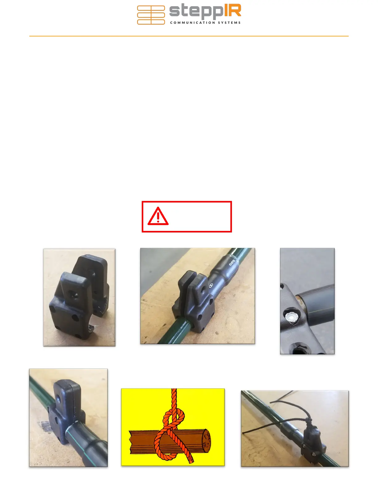
There are two pieces to the element truss couplers (PN 10-1510-21) as shown in Figure 7.41. The cou-
plers are mounted on each side of the loop, located at the outer joint of the telescoping poles as shown
in Figure 7.42. The truss coupler butts up against the edge of the polyolefin heat shrink.
There are nut trays molded on one side of the truss coupler, recessed so the nut can rest inside, as
shown in Figure 7.43. These are handy for holding the 6-32 Nylock nut (PN 60-0014) when tightening,
but you will need to position your finger over the nut to keep it from spinning when you thread on each of
the 6-32 x 7/8” pan-head machine screw (PN 60-0014-01). Align the truss coupler so that the Dacron
rope hole axis is parallel with the ground (coupler is perpendicular to ground) as shown in Figure 7.44.
Do not over tighten the screws. The coupler halves do not need to bottom out against themselves, a
small gap is fine.
The Dacron truss cord is provided in a single piece and will need to be trimmed as you progress with the
installation of the end trusses. Thread the Dacron cord through the truss coupler, leaving approximately
ten inches of truss cord sticking out of the hole. Tie four half-hitches and leave approximately four inches
of spare rope after the knots are tied. Figure 7.45 shows the proper way to tie a half-hitch. When fin-
ished, melt the end of the Dacron rope with a lighter so that it does not fray and apply electrical tape so
that the leader of the Dacron rope is secured to the truss line. Figure 7.46 shows a tied truss line before
electrical tape is applied.
Figure 7.43
Figure 7.45
Figure 7.41
Figure 7.42
Figure 7.44
Figure 7.46
Use anti-seize on
all stainless
hardware!