42
13406 SE 32nd St, BELLEVUE WA, 98005 WWW.CONSUMER.STEPPIR.COM TEL: (425)-453-1910
Section 7.3: Installing the Truss Support Mast
SKIP TO PAGE 46 IF YOU DO NOT HAVE THE 40/30 LOOP
The great advantage of telescoping fiberglass poles are that they are both flexible and extremely strong. This is a
significant advantage for such adverse weather situations as high winds, icing, or snow accumulation. The only
negative to this, is because of the flexibility, there is a slight natural “droop” at the element ends. This droop has no
impact whatsoever on performance, but some people do not care for the look. For primarily aesthetics purposes,
we offer the 40/30 loop end truss kit which allows for the leveling of the loop elements to the same level as the
straight elements. This makes for a better overall profile of the Yagi. The hardware below will be found in the 39’
element truss kit (PN 72-0018-31).
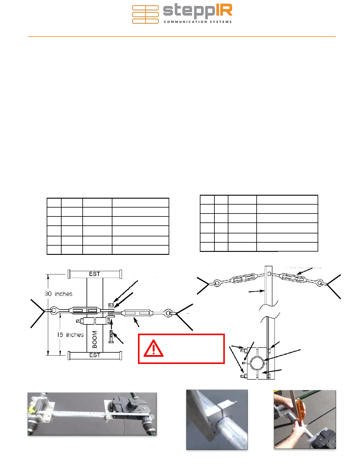
The truss mast needs to be mounted so that it is centered on the halfway point between the EHU’s EST center-
point and the return tube center-point. The overall length between the two center-points is 30 inches, so the halfway
point is 15 inches. Make a mark on the boom 15 inches between the two center-points as shown in Figure 7.33.
Locate the truss support (E) and two 1-3/4” aluminum saddle halves (F). Place the saddles so that the edge of the
saddle is on the edge of the mark as shown in Figure 7.34 (be sure this is the same edge as the one on the truss
support that the turnbuckles bolt to). This will ensure that the support is indeed on the center point. Insert two of the
5/16” x 3-1/2” hex head bolts (I) and secure with 5/16” Nylock nuts (G). Remember to use anti-seize on the stain-
less steel fasteners. Level the support (perpendicular to the element brackets) before tightening as shown in Fig-
ure 7.35. After tightening, insert a set screw (K) into the exposed saddle and tighten.
Attach each of the 4” stainless steel turnbuckles (C) using the 1/4” x 1-1/4” hex head bolt (D), two of the 5/16” stain-
less steel flat washers (B) and 1/4” Nylock nuts (A) as shown in Figure 7.31. The keys below are used for both
drawings, they are not separated by top or side view drawings.
Figure 7.33
40/30 ELEMENT TRUSS KIT
Figure 7.34
Key Qty Part # Description
F 2 10-1601-03 1-3/4” Aluminum saddle
G 2 60-0046 5/16” SS Nylock nut
I 2 60-0065 5/16” X 3-1/2” SS hex bolt
J 1 N/A Antenna Boom
K 1 60-0112 10-32 x 1/4” SS Set Screw
A
B
C
D
Figure 7.31—Top View
G
E
C
I
J
F
Figure 7.32—Side View
K
Figure 7.35
Use anti-seize on
all stainless
hardware!
Key Qty Part # Description
A 1 60-0030 1/4” SS Nylock nut
B 2 60-0033 5/16” SS washer
C 2 60-0083 4” SS turnbuckle
D 1 60-0110 1/4” X 1-1/4” SS hex bolt
E 1 10-1054-02 30m / 40m truss support