Tech Support: consumer.steppir.com/support | 425.453.1910 | support@steppir.com
23
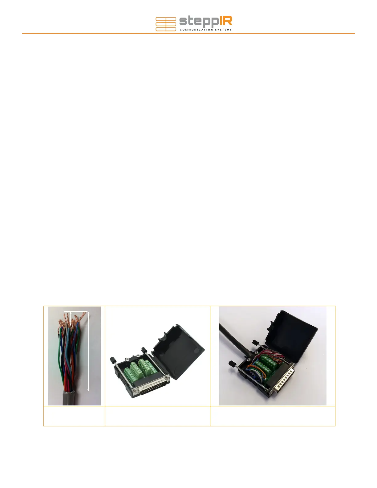
Figure 1.20 Figure 1.30 Figure 1.31
Section 1.5: Preparing the control cable (skip if you have pre-wired cable)
1. Strip the jacket and aluminum shielding off of the control cable as shown in figure 1.20, approximately
2.75” from end of control cable, being careful not to damage the individual wires.
2. Strip the plastic insulation off of each of the control cable wires, approximately 0.25” in length should be
bare wire.
Section 1.6: Connecting control cable to the DB25 Field Splice
(skip if you have pre-wired cable)
1. Apply the provided dielectric grease to the exposed copper portion of each wire.
The terminals may be closed by default. If so, turn the terminal screw counter clockwise ~10 turns to
open it before inserting the wires.
2. Connect each wire to the appropriate terminal and tighten using a flat head screwdriver.
3. Consult the table on the next page for the correct wiring sequence.
4. Position the control cable between the cable clamp halves as shown in figure 1.31. Electrical tape can be
wrapped around the cables to increase their thickness if necessary.
5. Tighten the two pan head screws until the cable is snug, but do not over-tighten.
6. Thread the two thumb screws into the connector face as shown in figure 5.23.
7. Plug the DB25 splice into the back of the controller, ensuring that it is fully seated, and twist the thumb-
screws to secure it. For first time setups it is common for this to be only partially installed, resulting in fault
codes on the controller.
WIRING
2.75”
0.25”