INSTALLATION
Installation
6 | DCE-C Trend www.stiebel-eltron.com
Note
Install the appliance flush to the wall. The wall must
have sufficient load bearing capacity.
8.2 Minimum clearances
≥50≥50
≥50
D0000079442
Maintain the minimum clearances to ensure trouble-free op-
eration of the appliance and facilitate maintenance work.
8.3 Water installation
!
Material losses
Carry out all water connection and installation work in
accordance with regulations.
Flush the water line thoroughly.
Taps
Use appropriate pressure taps. Open vented taps are not per-
missible.
Permissible water line materials
- Cold water inlet line:
Pipes made from galvanised steel, stainless steel, copper or
plastic
- DHW outlet line:
Pipes made from stainless steel, copper or plastic
!
Material losses
If plastic pipework systems are used, take into account
the maximum inlet temperature and the maximum per-
missible pressure.
Flow rate
Ensure that the flow rate for switching on the appliance is
achieved.
If the required flow rate is not achieved when the draw-off
valve is fully open, remove the flow limiter from the cold
water inlet.
If required, the pressure in the water installation can also be
raised.
9. Installation
Factory settings
Trend
Trend
Connected load in kW @ 220V 8.0 12.0
@ 230V 8.7 13.1
Standard installation
Trend
Trend
Electrical connection from below, installa-
tion on finished walls
x x
Water connection, installation on finished
walls
x x
For further installation options, see chapter "Alternative instal-
lation methods".
9.1 Standard installation on finished walls
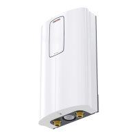
Opening the appliance
D0000073641
Open the appliance by undoing the screw and lifting up the
appliance cover.
Preparing the power cable
D0000077179
Prepare the power cable.
Position on finished walls Dimension A Dimension B
Bottom, centre 30 120
Bottom, left side of appliance 20 90
Bottom, right side of appliance 20 90
Top, right side of appliance 20 80
Position on unfinished walls Dimension A Dimension B
Bottom 20 90
Top 20 80
 Loading...