14
Pushing the cylinder module towards the function module
Push the cylinder module carefully towards the function
module, so that the rear r.h. adjustable foot of the cylinder
module is near the recess in the joining bracket.
5.3 Connecting modules
Cylinder temperature sensor and anode cable
Remove the cable tie that tie together the electrical cables
of the anode terminal and the cylinder temperature sensor
lead.
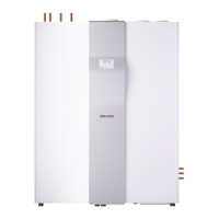
Pull the connecting cables/leads of the anode and the cylin-
der temperature sensor through the aperture located on the
top r.h. side in the cylinder module.
1
26_04_01_0556
1 Aperture in the thermal insulation for sensor lead of the cy-
linder temperature sensor
Push the cylinder temperature sensor from the top through
the aperture in the thermal insulation.
Insert the cylinder temperature sensor into the lower cylin-
der sensor well.
Note
It is possible that the cylinder module and the function
module will still be too far apart to be able to insert the
cylinder temperature sensor into the sensor sleeve.
If so, you can insert the cylinder temperature sensor into
the sleeve at a later point. What is important is that you
route the sensor lead through the insulation before you
install the terminal bracket.
The top sensor sleeve is required either in connection with buffer
operation on convector heaters (see chapter „Settings/ DHW/
DHW buffer mode“) or for economy mode (see chapter „Connec-
ting internal cables“).
Pushing the cylinder and the function modules together
Note
An air hose to capture the differential pressure runs
along the l.h. side of the function module. This air hose
must run inside the curved groove cut into the thermal
insulation.
Ensure that this air hose is seated correctly.
Note
The adjustable feet must not be fully screwed in, other-
wise you will not be able to push the joining bracket
between the bottom panel and the foot.
Push the cylinder module further towards the function mo-
dule, so that the rear r.h. adjustable foot of the cylinder mo-
dule is pushed into the recess in the joining bracket.
The lower joining bracket ensures that the cylinder module is
automatically pushed into its final position.
Level the cylinder module and the function module vertically
to the same height by turning the adjustable feet.
Note
The cylinder module drops 4 to 5mm when its cylinder
is filled.
Turning anti-clockwise exposes more of the adjustable feet, mea-
ning the appliance moves upwards. The cylinder module must be
snug against the function module.
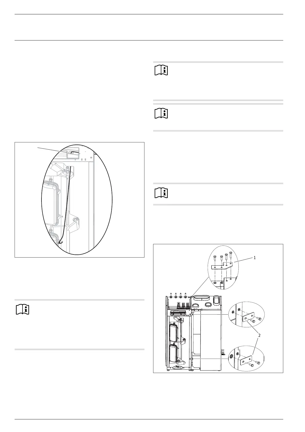
Connection top back
D0000076677
1
2
1 Joining plate
2 Horizontal locking bracket
Connect the function module and the cylinder module at
the top back by positioning joining plate and inserting two
screws each through the joining plate into the function mo-
dule and the cylinder module.
 Loading...