As the appliance can produce negative pressure in the installa-
tion room, we recommend using a tightly sealing door between
the installation room and the living space containing combustion
equipment. If, due to its use, the installation room is connected
to the extract air system, you must also make special arrange-
ments for a supply air vent in the installation room, to prevent
any further increase in the negative pressure in this room. The
negative pressure created by the appliance in the installation room
is heavily influenced by the pressure drop in the outdoor air line.
For this reason, the outdoor air line in particular should be as
short as possible.
Note
The maximum permissible pressure drop (see chapter
"Specification/ Data table/ Max. pressure drop, outdoor
air") must not be exceeded.
During regular operation, the ventilation unit promotes a balanced
air flow rate and no pressure differences occur. Do not switch
off the mechanical ventilation component of the appliance if the
combustion equipment is in operation.
!
WARNING Injury
If no safety equipment is installed, open the parameter
"STOVE/ FIREPLACE" and select the option "N/C MONI-
TORING". This option switches off the heat pump as soon
as mechanical ventilation is deactivated.
!
WARNING Injury
If you notice flue gas escaping from the combustion
equipment, switch off any air extraction appliances, e.g.
exhaust air extractor hoods, exhaust air tumble dryers,
the central vacuum cleaning system and the ventilation
unit. Interrupt any voltage supply to the ventilation unit,
including the integral heat pump, via the fuses/MCBs in
your fuse box/distribution board.
Open windows and doors.
The safety equipment also switches off the DHW heating. If the
dual mode point is undershot, the emergency/booster heater for
DHW heating switches on, resulting in an increased electrical
energy demand.
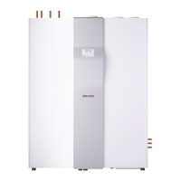
3. Appliance description
The appliance comprises a function module and a cylinder module
that are supplied as separate shipping units. The wider module
with the air hose connections in the cover is the function module.
The components required for installation are in a separate carton
inside the function module packaging.
3.1 Standard delivery
!
Material losses
Never install the push-fit connectors in the DHW line.
Never install the push-fit connectors to the solar flow or
solar return connections. Only install the push-fit con-
nectors in the heating circuit.
The following are delivered with the appliance:
- Operating instructions
- Installation instructions
- Notification list
- Transport aid, comprising two angled brackets with screws
for fixing to the appliance
- Programming unit
- Outside sensor
- Four adjustable feet for the cylinder module
- Eight sliding blocks for easier positioning of the appliance
- Hose clips to secure the air hoses
- Adhesive tape to seal the inner hose to the hose connector
- PE plate for connection to a geothermal heat exchanger or an
external fresh air intake
- Fixing materials (screws, washers, etc.)
- Two straight push-fit connectors for the hydraulic connection
of the function and cylinder modules
For connection to the heating circuit:
- Two straight push-fit connectors
- One filter ball valve
- One ball valve
- Two 90° push-fit connectors
- Four straight pieces of pipe with G1 union nut
3.2 Required accessories
- Air hose with thermal insulation, 4m
- Thermally insulated wall outlet with external wall grille
3.3 Additional accessories
- Additional programming unit with wall mounted casing
- Spare filter set
- Diverter hood (enables the appliance to be sited in rooms
with head heights between2.2 and 2.5m)
- Silencer DN315
- Segmented anode
- DHW circulation pipe set
- Filter box (for installation in round DN160 ventilation pipes)
- ISG: Internet Service Gateway
- PK 10 : Condensate pump
- Safety temperature controller for underfloor heating system
- Temperature sensor for the second DHW cylinder (sensor
type Pt1000)
- ZKA WP : Condensate drain with outlet siphon
3.4 Appliance functions
The supply air fan induces outdoor air into the appliance. The
extract air fan draws stale air from the living areas into the appli-
ance. Outdoor air and extract air are routed through particle air
filters into separate ducts of a cross-countercurrent heat exchan-
ger. Inside the cross-countercurrent heat exchanger, the outdoor
air is heated and channelled into the living space as supply air.
The extract air cools down inside the cross-countercurrent heat
exchanger and is routed as exhaust air first through the evaporator
and then outdoors.
 Loading...