3
- Observe all applicable national and regional re-
gulations and instructions during installation.
- The appliance is not approved for outdoor
installation.
- Observe the requirements concerning the ins-
tallation room (see chapter „Specification/ Data
table“).
- Observe minimum clearances (see chapter „Pre-
parations/ Installation site“).
- The connection to the power supply must be in
the form of a permanent connection. Ensure the
appliance can be separated from the power sup-
ply by an isolator that disconnects all poles with
at least 3mm contact separation.
- Observe the fuse protection required for the ap-
pliance (see chapter „Specification/ Data table“).
- Drain the appliance as described in chapter
„Shutdown“.
- Install a type-tested safety valve in the cold water
supply line.
- The maximum pressure in the cold water supply
line must be at least 20% below the response
pressure of the safety valve. If the maximum
pressure in the cold water supply line is higher,
install a pressure reducing valve.
- Size the drain so that water can drain off unimpe-
ded when the safety valve is fully opened.
- Fit the discharge pipe of the safety valve with
a constant downward slope and in a room free
from the risk of frost.
- The safety valve discharge aperture must remain
open to atmosphere.
1. General information
These instructions are intended for qualified contractors.
1.1 Relevant documents
336513 Operation
337705 Commissioning / Notification list
1.2 Information on the appliance
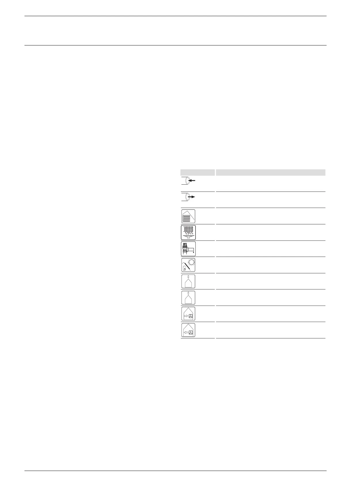
Connections
Inlet/ intake
Drain/ outlet
Heating
Condensate
Safety valve drain
Solar thermal
Outdoor air
Exhaust air
Extract air
Supply air
1.3 Standardised output data
Information on determining and interpreting the specified stan-
dardised output data
1.3.1 Standard : EN 13141-7 , EN 14511 , EN 16147
The output data specifically mentioned in text, diagrams and
technical datasheets has been calculated according to the test
conditions of the standards shown in the heading of this section.
However, there is a deviation from the standard EN14511 in the
performance specifications for inverter driven air source heat
pumps with source temperatures > -7°C, as these are partial
load values. The associated percentage weighting in the partial
load range can be found in EN14825 and EHPA quality label re-
gulations.
Generally, the test conditions stated above will not fully match
the conditions found at the installation site of the system user.
 Loading...