19
WARNING Electrocution
Only components that operate with safety extra low
voltage (SELV) and that ensure secure separation from
the mains voltage supply may be connected to the low
voltage terminals of the appliance.
Connecting other components can make parts of the ap-
pliance and connected components live.
Only use components which have been approved by
us.
!
Material losses
The specified voltage must match the mains voltage. Ob-
serve the type plate.
!
Material losses
The cable entries at the back of the appliance are closed
with cable grommets. To prevent an ingress of water, cut
as small a hole as possible in the cable grommet.
Note
The leakage current of this appliance can be >3.5mA.
5.9.1 General information
The electrical data is given in the chapter „Specification/Data
table“.
Note
If cooling is to be provided by means of an area heating
system, always use an external programming unit (see
chapter "Appliance description/ Further accessories").
An external programming unit can capture the relative
humidity in the air, helping to prevent humidity conden-
sing on surfaces inside the room.
Cable routing
Push all connecting cables and sensor leads through one of
the „Entry electrical cables“ ducts in the back panel of the
function module.
Safety temperature controller for underfloor heating system
!
Material losses
In order to prevent excessively high flow temperatures in
the underfloor heating system in the event of a fault, we
always recommend using a safety temperature controller
to limit the system temperature.
Safety equipment for simultaneous operation of ventilation
unit and combustion equipment
XD03-13/14 : Connect the safety equipment using a floating
contact.
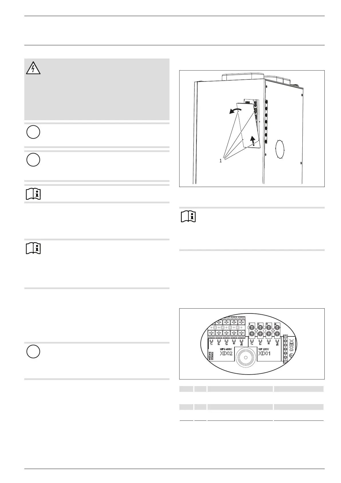
5.9.2 Control panel
D0000062335
1
1 Control panel fastening screws
Undo the fixing screws of the control panel cover.
Note
A serrated washer is used on one of the fastening screws
to earth the control panel cover.
When you refit the control panel cover after working at
the control panel, place the serrated washer behind the
fastening screw.
The control panel cover is held in place at the lower end by a tab
that slots behind the appliance side panel.
Push the control panel cover upwards and pull out at the
bottom to remove it from the appliance.
5.9.3 Heat pump (compressor) and electric emergency/
booster heater
D0000038968
XD01
WP Heat pump L1 Compressor
L2 Heat pump fan
XD02
MFG Electric emergency/booster heater
of the multifunction assembly
For optimum function, connect all three stages of the electric
emergency/booster heater.
 Loading...