INSTALLATION
Electrical connection
14 | WPM www.stiebel-eltron.com
4.2 Installation location
The device is designed solely for wall mounting.
Install the device close to the heat pump.
Install the device on a smooth installation surface. This will
make it easier to lay the electrical cables.
Ensure that enough space is available to the left or right of
the device for the WPE heat pump extension, if required.
Ensure that the back of the wall mounting enclosure is not
accessible once mounted.
Protect the equipment in use against humidity, dirt and
damage.
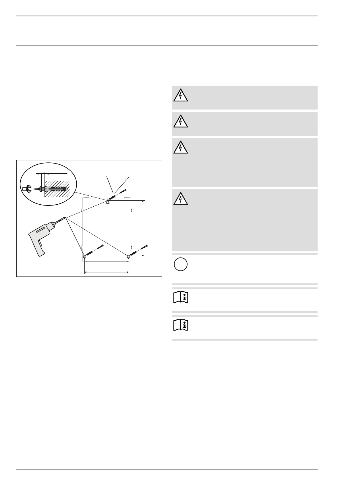
4.3 Wall mounting
276
353
Ø 4 x 35
Ø 6
2,6 - 3,0
D0000061424
Mark the holes to be drilled.
Drill the holes and insert suitable rawl plugs.
To secure the top of the enclosure, insert a screw far enough
into the corresponding rawl plug that the enclosure can just
still be hung onto the screw head.
Then secure the bottom of the enclosure with two further
screws.
5. Electrical connection
5.1 General
WARNING Electrocution
Carry out all electrical connection and installation work
in accordance with national and regional regulations.
WARNING Electrocution
Isolate the heat pump from the power supply when
carrying out any work.
WARNING Electrocution
The connection to the power supply must be in the form
of a permanent connection. Ensure the appliance can be
separated from the power supply by an isolator that dis-
connects all poles with at least 3 mm contact separation.
This requirement can be met by using contactors, circuit
breakers, fuses/MCBs, etc.
WARNING Electrocution
Only components that operate with safety extra low
voltage (SELV) and that ensure secure separation from
the mains voltage supply may be connected to the low
voltage terminals of the appliance.
Connecting other components can make parts of the ap-
pliance and connected components live.
Only use components which have been approved by
us.
!
Material losses
When connecting up, note the maximum load capac-
ity of the relay outputs (see chapter “Specification/
Data table”).
Note
The specified voltage must match the mains voltage. Ob-
serve the type plate.
Note
In conjunction with the WPM heat pump manager, use
the HSM mixer servomotor.
When connecting the power, observe the relevant electrical
connection diagram for the heat pump.
Protect the device on site with a 6A circuit breaker.
The supply voltage at terminal L and the phase L' – switched by
the power supply utility – must be routed via the same residual
current device, as they share a neutral conductor in the WPM.
Ensure that L and L' are in phase.
Disconnect all heating system poles from the mains power
supply before installation.
No fuses/MCBs for connected consumers are provided in the
WPMor in the wall mounting enclosure. A fuse for connected
consumers may be connected in series via terminal L* or pumps
L (see also heat pump connection diagram).

 Loading...


