EasyManuals Logo

STIEBEL ELTRON WPM Installation

STIEBEL ELTRON WPM
To Next Page IconTo Next Page
To Previous Page IconTo Previous Page
Page #6 background imageLoading...
Page #6 background image
INSTALLATION
Elektrischer Anschluss
6 | WPM www.stiebel-eltron.com
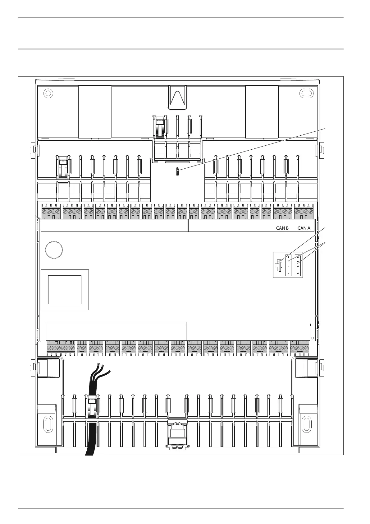
Anschlussbelegung
X2.2 X2.3 X2.4 X2.5 X2.6 X2.7 X2.8 X2.9 X2.10 X2.11 X2.12 X2.13 X2.14 X2.15
X1.1
CAN A
X1.19
CAN A
X1.18
CAN B
X1.17X1.16X1.15X1.14X1.13X1.12X1.2
CAN B
X1.3 X1.4 X1.5 X1.6 X1.7 X1.8 X1.9 X1.10 X1.11
X2.1
D0000061425
2
3
1
1 Haltedorn für das Anschlusskabel der Bedieneinheit
2 microSD-Kartenslot
3 CAN-Bus für Bedieneinheit
Legen Sie das Anschlusskabel der Bedieneinheit über den Haltedorn.

Table of Contents

Other manuals for STIEBEL ELTRON WPM

Questions and Answers:

Question and Answer IconNeed help?

Do you have a question about the STIEBEL ELTRON WPM and is the answer not in the manual?

STIEBEL ELTRON WPM Specifications

General IconGeneral
BrandSTIEBEL ELTRON
ModelWPM
CategoryHeat Pump
LanguageEnglish

Related product manuals