23
cuit data, the max. set mixer flow temperature
is used for the controller, which regulates to
this value.
18
MIXER DYNAMIC
Mixer run time
Setting range 60 to 240
This setting enables a matching of the mixer
characteristics. Setting 60 to 240 means 6 K to
24 K control deviation.
The system scans every 10 s, and the mini-
mum ON duration for the mixer is 0.5 s. The
mixer does not respond inside the dead zone
of ±1 K from the set value.
Example for the setting 100 = 10 K (see fig
below).
The control deviation (set mixer temperature
– actual mixer temperature) is 5 K. The mixer
opens for 5 s, then pauses for 5 s and starts
again from the beginning.
The control deviation (set mixer temperatu-
re – actual mixer temperature) is 7.5 K. The
mixer opens for 7.5 s, then pauses for 2.5 s
and starts again from the beginning.
In other words, the smaller the control devia-
tion, the shorter the mixer ON time and the
longer its pauses.
A reduction of the mixer dynamic value with
static control deviation increases the ON du-
ration and reduces the pauses.
19
FROST PROTECT
To prevent the heating system freezing up,
the heat pumps are started at the set frost
protection temperature; the reverse hysteresis
is 1 K.
20
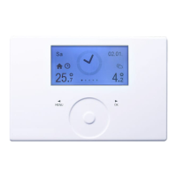
SELECT REM CON
The FE7 remote control can be selected for
both heating circuits
Using the „Select rem com“ parameter you
can predetermine for which heating circuit the
remote control should be active. Under the
„Room temperature 1 or 2“ on control level
2 you can scan, subject to the remote control
pre-selection, the actual room temperature.
21
FE CORRECTION
This parameter enables the calibration
of the room temperature.
22
Room influence
For FE7 remote control
Standard setting 5 adjustable from ---- via 0 to
20 dashes (----) on the display:
With the FE7 remote control connected, the
room temperature sensor only serves to re-
cord and display the actual room temperature;
it has no influence on the control unit. With
the setting „0 to 20“ you can adjust the set
room temperature for the heating circuit on
the FE7 remote control by ±5 K. This set value
adjustment applies respectively for the current
heating time, not for the setback time.
Similarly, setting „0 to 20“ serves to control
the room temperature-dependent night set-
back. This means, the heating circuit pump is
switched OFF at the point of changeover from
the heating into the setback phase. It remains
OFF, until the actual room temperature first
falls below the set room temperature. After-
wards the system regulated in weather-com-
pensated mode.
Set the room sensor influence to ≥ 2, if you
want the room temperature to be taken into
account. The room sensor influence has the
same effect as the outside temperature sensor
has on the return temperature. Only this ef-
fect is 2 to 20 times greater by the set factor.
Room temperature-dependent return tem-
perature with outside temperature inuence
With this type of control, a control cascade is
formed from weather-compensated and room
temperature-dependent return temperature
control. In other words, the weather-com-
pensated return temperature control creates
a pre-selection of the return temperature,
which is corrected by the overlaid return
temperature control in accordance with the
following formula:
∆ϑR = (ϑRset - ϑRact) * S * K
A substantial proportion of the control is
already taken care of by the weather-com-
pensated control, the room sensor influence
K can be set lower than with a pure room
temperature control (K=20). The figure below
indicates the control unit method of operati-
on with the set factor K=10 (room influence)
and a heating curve S=1.2
Room temperature control with weather-
compensation.
This type of control offers two substantial
advantages:
Incorrectly set heating curves are corrected
by the room sensor influence K; whilst the
smaller factor K makes the control unit more
stable.
However, observe the following for all control
units with room sensor influence:
20
30
40
20
50
60
70
80
90
Vorlauftemperatur [°C]
15 16 1917 18 21 22 23 24 25
Raumtemperatur [°C]
0
10
20
30
40
0
50
60
70
80
90
Vorlauftemperatur [°C]
20
-20
Außentemperatur [°C]
0
10
15
10
5
-5
-10
-15
Heizkurve
S = 1,2
$*
= S K (*
- *)
witterungsabhängiger Vorlaufsollwert bei *
A
= -10°C
witterungsabhängiger Vorlaufsollwert bei *
A
= 0°C
witterungsabhängiger Vorlaufsollwert bei *
A
= 10°C
Raumfühlereinfluss bei K = 10 und S = 1,2
und Regelabweichung +/- 2 K
R
R soll R ist
26_03_01_0098
Room inuence
Weather-compensated set ow temperature ϑ = -10°C
Flow temp. [°C]
Flow temp. [°C]
Room temp. [°C]
Room inuence at K=10 and S=1,2
Outdoor temp. [°C]
Heating curve
S=1,2
Weather-compensated set ow temperature ϑ=0°C
Weather-compensated set ow temperature ϑ=10°C
∆ϑRoom= S * K * (ϑSet Room - ϑSet Room )

 Loading...


