9
26_03_01_0077
1,5
2
1,2
1
0,6
0,4
0,2
2,53
20
18
16
14
12
10
8
6
4
2
0
-2
-4
-6
-8
-10
-12
-14
-16
-18
-20
100
80
60
40
20
Außentemperatur [°C]
Heizkreis 2 WP-Vorlauftemperatur [°C]
Heizkreis 1 WP-Rücklauftemperatur [°C]
0,8
20
18
16
14
12
10
8
6
4
2
0
-2
-4
-6
-8
-10
-12
-14
-16
-18
-20
Außentemperatur [°C]
70
60
50
40
30
20
Tag-Betrieb
Absenk-Betrieb
Rücklauf- / Vorlauftemperatur [°C]
20
18
16
14
12
10
8
6
4
2
0
-2
-4
-6
-8
-10
-12
-14
-16
-18
-20
Außentemperatur [°C]
Rücklauf- / Vorlauftemperatur [°C]
70
60
50
40
30
20
geänderte Heizkurve
26_03_01_0078
26_03_01_0079
Heating curve diagram
One heating curve respectively can be adjusted for heating circuit 1 and heating circuit 2.
At the factory, heating curve 0.6 is set up for heating circuit 1 and heating curve 0.2 for
heating circuit 2. These heating curves relate to a set room temperature of 20 °C.
Adjustment of programmed changeover between day/setback mode
The figure shows a standard heating curve with a slope of 0.8, relative to a set room tempe-
rature for day mode of 20 °C. The lower curve represents the setback curve. For this, the set
room temperature for setback mode of 15 °C is used, in other words the heating curve is
subjected to a parallel offset.
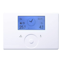
Open the control ap.
Matching a heating curve to actual conditions
Example: During spring and autumn, the return or flow temperature of a heating system is
too low at an outside temperature between 5 and 15 °C, but is OK at outside temperatures
of ≤ 0 °C. This problem can be remedied with parallel offset and a simultaneous reduction of
the heating curve. Prior to this adjustment, heating curve 1.0 was adjusted, relative to a Set
room temperature of 20 °C. The dotted line indicates the modified heating curve at 0.83 and
a modified set room temperature at 23.2 °C.
Heating Curves
Back
Heating Curves
Heating Circuit 1, HP Return temperature [°C]
Heating Circuit 2, HP Flow temperature [°C]
HP Return temp. / Flow temp. [°C]
Day operation
Set-back operation
Outdoor temperature [°C]
HP Return temp. / Flow temp. [°C]
modified Heating curve
Outdoor temperature [°C]
Outdoor temperature [°C]

 Loading...


