33BR 500, BR 550, BR 600
– Remove the cam followers,
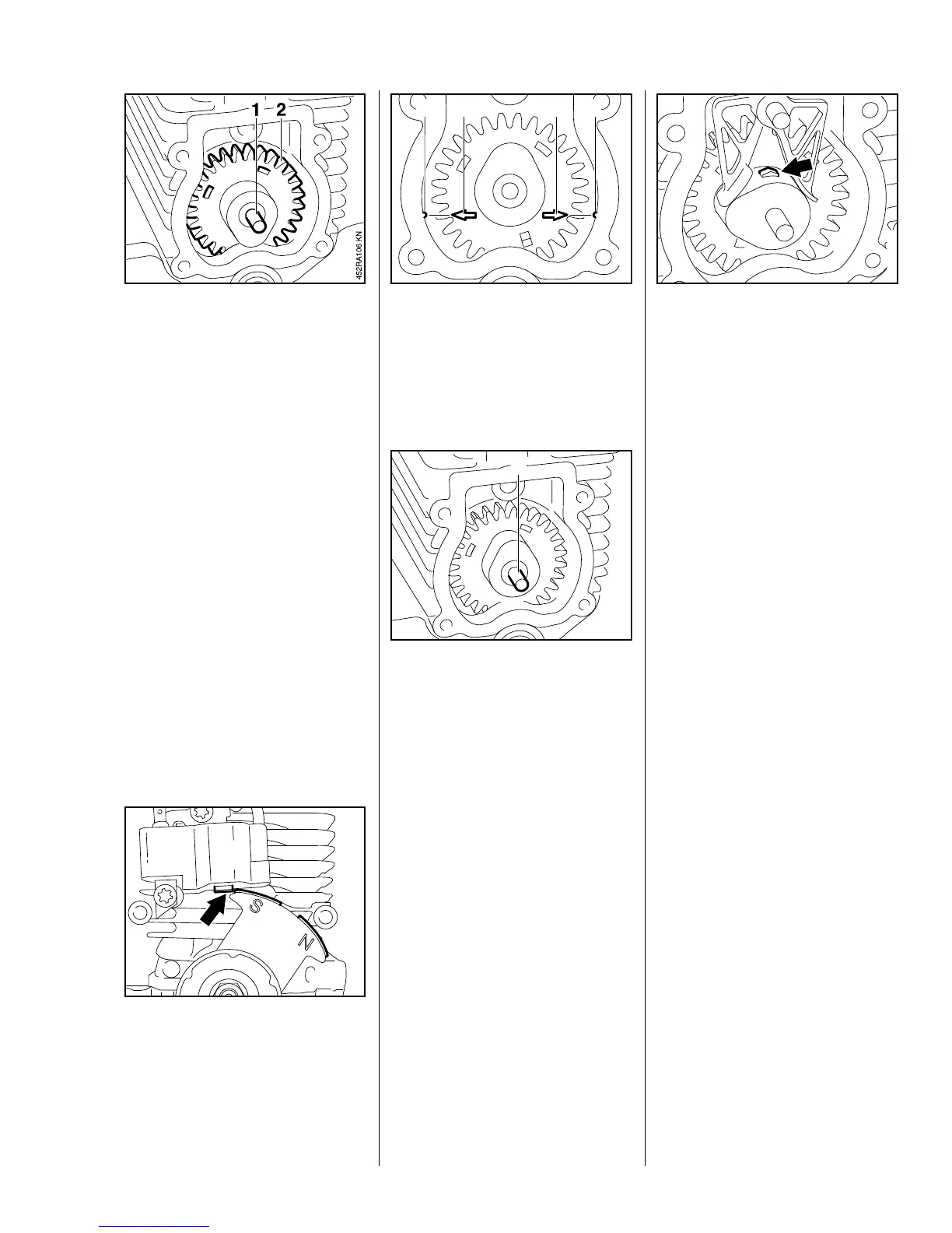
b 7.4
: Pull out the pin (1).
: Remove the cam gear (2).
Install in the reverse sequence.
Coat all parts with two-stroke
engine oil before installing.
: Rotate the crankshaft until the tip
(arrow) of the flywheel lines up
with the ignition module as
shown.
: Fit the cam gear so that the
marks (2) and (3) and in
alignment with the notches (1)
and (4) in the cylinder.
: Install the pin (1).
The marks must not move out of
position while the cam gear is being
fitted.
– Rotate the crankshaft until the
cam lobe on the cam gear points
downward.
– Install the cam followers, b 7.4
– Remove cam gear cover, b 7.3
: Check free movement and
function of decompression
system lever (arrow).
– Lever must project about 2 mm
from the cam.
– Push decompression system
lever counterclockwise. The lever
must move freely and retract fully.
If the lever is difficult to move, worn
or not visible, install a new cam
gear, b 7.5.
7.5 Cam Gear 7.5.1 Decompression System
RA_452_00_01_02.book Seite 33 Donnerstag, 16. Februar 2012 11:52 11

 Loading...