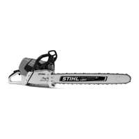
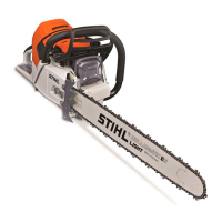
26 MS 650, MS 660
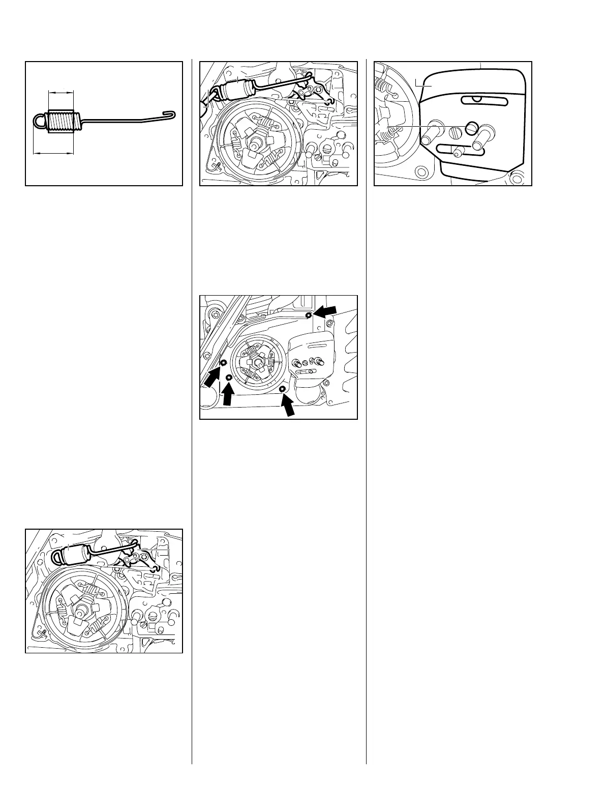
: The turns of brake spring must be
tightly against one another in the
relaxed condition. If this is not the
case, replace the brake spring.
Check correct position of
protective tube:
aa
b
VA
176RA046
a = 18 mm
b = 33 mm
: Hook the brake spring (1) to the
brake lever (2).
178RA034
VA
1
2
: Use the assembly tool (2)
1117 890 0900 to attach the
brake spring (1) to the anchor pin
(arrow).
178RA035
VA
1
2
– Place cover in position.
: Insert screws (arrows) and
tighten them down firmly – b 3.5
– Install the clutch drum/chain
sprocket – b 5.1
178RA025
VA
: Fit the side plate (2) over the
collar screws and push it against
the crankcase.
: Fit the screw (1) and tighten it
down firmly.
– Mount the guide bar and chain
VA
138RA004
1
2
sprocket cover. Tighten down
nuts on the chain sprocket cover
– b 3.5
– Check operation of chain brake –
b 5.5.1