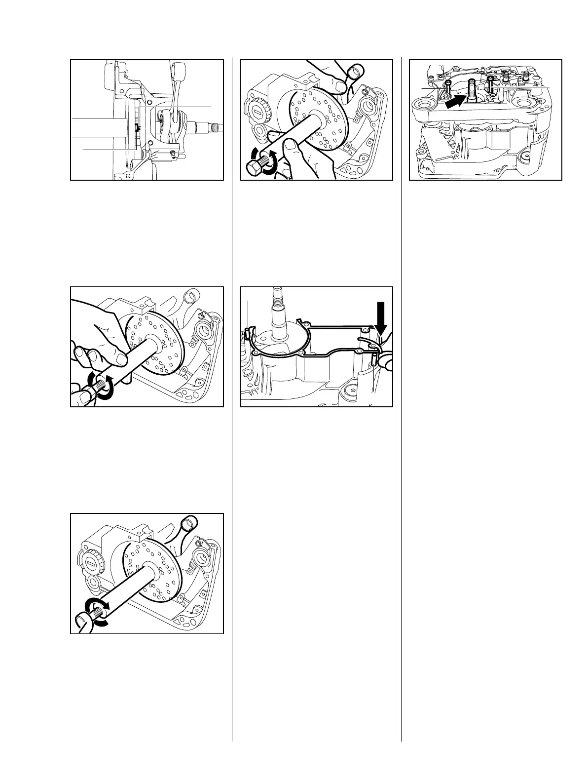
45MS 650, MS 660
: Screw threaded sleeve (2) to
thread (1) of crankshaft stub.
178RA217
2
1
VA
: Hold the spindle steady and
rotate the service tool counter-
clockwise until the drilled plate
butts against the crankcase.
178RA218
VA
: Turn the spindle clockwise until
the crankshaft locates against
the ball bearing.
The connecting rod must point
toward the cylinder flange while the
crankshaft is being installed.
178RA219
VA
: Hold the crankshaft steady,
release the spindle counter-
clockwise and then unscrew the
service tool, also counter-
clockwise.
178RA220
VA
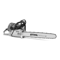
: Place new gasket (arrow) on the
flywheel side of the crankcase.
: The gasket is held in position by
the pins (1).
– Fit bar mounting studs at clutch
side – b 5.7
178RA221
VA
1
1
– Lubricate straight stub of
crankshaft (arrow) with oil.
– Fit crankshaft stub in the ball
bearing.
: To prevent the crankcase halves
and gasket twisting, fit M5x72
178RA222
1
1
VA
screws (arrows) in two crankcase
holes and tighten them down as
far as stop.