ASTOTHERM PLUS Instructions for Use
44
12.2 Set up for electrical tests
For measuring the protective earth resistance, the insulation resistance and the
equipment/earth leakage current, the following test set up can be used:
Measurement (True RMS)
(see also IEC/EN 62353)
Use connection to
electrical safety analyzer
Protective earth resistance
Equipment leakage current
(alternative method)
Connection 1
(and possibly connection 2,
depending on the used safety
analyzer)
Earth leakage current N.C.
(direct method)
Earth leakage current S.F.C
(direct method, N open)
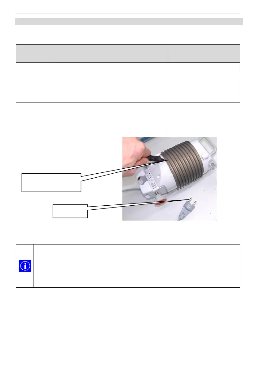
Abb. 7: Test set up for measuring
In order to achieve a sufficient accurate measurement result, during the
measurement of the protective earth resistance, good electrical contact
with the metal of the heat exchanger must be established.
On the top of the heat exchanger (backside) is a small bare spot to
make the contact with the probe. At this point the (insulating) anodic
coating of the heat exchanger is penetrated by the manufacturer’s test.
Connection 2:
Probe to heat exchanger
(=touchable and conductive)


 To Next Page