7
Wiring the SR500/SR500PS
NOTE: THE STINGL-SWITCH CANNOT BE USED/RELIED ON AS AN ELEC-
TRICAL DISCONNECT MEANS. A SEPARATE DISCONNECT MEANS MUST
BE PROVIDED. A CERTIFIED ELECTRICIAN IN ACCORDANCE WITH THE
NATIONAL ELECTRICAL CODE MUST COMPLETE ALL ELECTRICAL
WORK.
The voltage selector switch on the right side of the metal case MUST BE SET to match the
incoming power. Damages to the unit due to improper power input WILL NOT be covered
by warranty. The unit is set to 230 volts at the factory, this will also be the correct setting
for 208 volt applications. For 110/115/120 volt pumps, set the selector switch to 115v.
Line
Voltage Option 1
High Voltage 120/240V Single Phase 3 HP Pumps (20AMP) or less
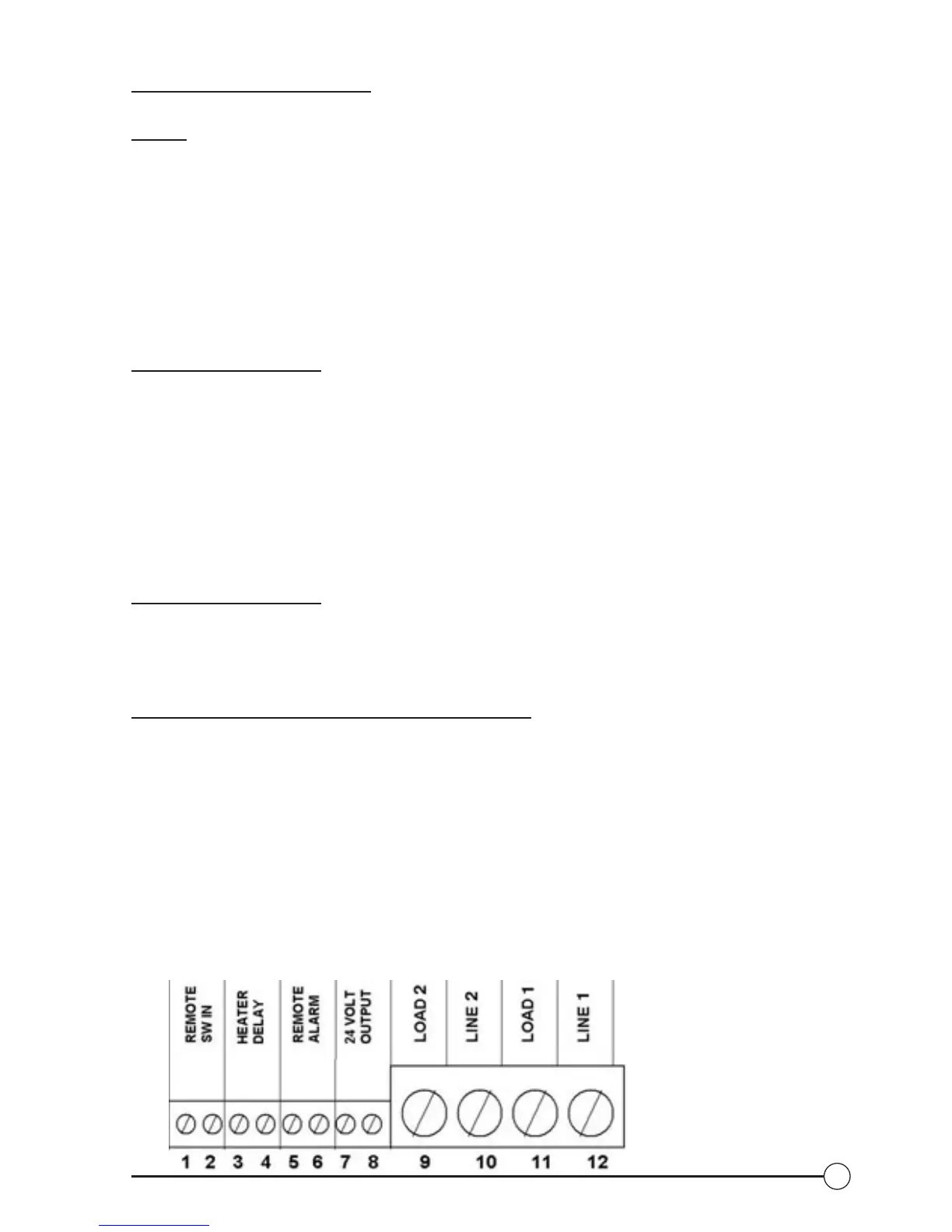
(See Fig. 3 for terminal locations)
1. Determine the operating input voltage of the pump, 120V or 240V. Set the red
input switch (located on the right side of SR-500) accordingly.
2. Wire incoming voltage to line terminals (#10 & #12)
3. Wire pump to load terminals (#9 & #11)
4. Connect line & load grounds to the green ground pigtail with wire nut.
5. For this scenario see Drawing 1 or 2
Line
Voltage Option 2
High Voltage 240/480/600 Triple Phase 3.5 HP pumps (20AMPS) or greater.
1. Set the red input switch (located on the right side of SR-500) to 115V
2. For this scenario see Drawing 3
Low
Voltage (See Fig. 3 for terminal locations)
1. Heater delay circuit (fireman’s switch) – connect heater delay circuit to contacts
(#3 & #4) on
terminal strip. NOTE: Heater delay must be enabled in set up menu – see
operating instructions
2. Remote powered alarms can be connected to terminals (#5 & #6), or the SR-
500 can power 24V alarms by jumping terminals (#6 & #7), and wiring alarm
to terminals (#5 & #8).
3. Remote interfaces such as Jandy
®
or ComPool
®
, pneumatic or solid-state
controls and external timer systems are connected to terminals (#1 & #2).
NOTE: The remote mode must be enabled in the on/start menu for remote
interfaces to operate properly.
Fig. 3: Terminal Diagram