POSIDRIVE
®
FDS 4000
STÖBER
ANTRIEBSTECHNIK
3. Physical Installation
4. Electrical Installation
3
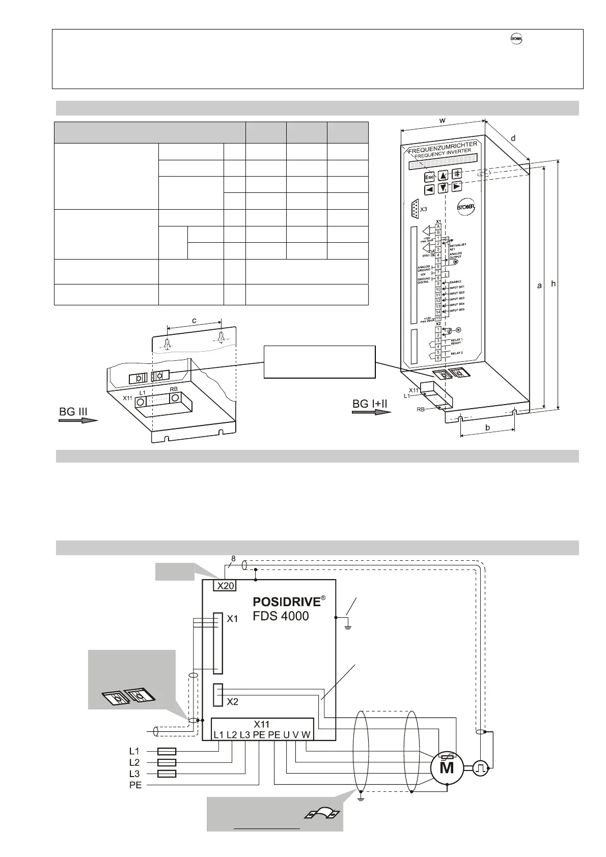
3 PHYSICAL INSTALLATION
Dimension in mm BG I BG II BG III
Height h 300 300 410
Width w 98 98 186
d1 176 268 268
Frequency inverter,
base plate
Depth
d2 158 250 250
Vertical a 282,5 282,5 392,5
above c --- --- 150
Base plate,
mounting holes
Hori-
zontal
below b 70 70 150
Min. free space
between adjacent units
Top/bottom: 100 (min.)
Right/left: 1 (min.)
Screws M5
d1 = Device depth including plug connector
3.1 Installation site
• Operate only in closed switching cabinet.
• Install inverter only in vertical position.
• Avoid installation over heat-producing devices.
• Ensure sufficient air circulation in switching cabinet.
(Minimum free space of 100 mm over and under the
device!).
• Keep installation site free of dust, corrosive fumes and all liquids (in
accordance with soil degree 2 in accord. with EN 60204/EN 50178).
• Avoid atmospheric humidity.
• Avoid condensation (e.g., by anti-condensation heaters).
• Use unpainted mounting plates with conductive surface (e.g.,
unpainted) to conform with EMC regulations.
4 ELECTRICAL INSTALLATION
EMC terminal only for
control cables
EMC terminal for
control lines on
bottom
Secure shield with a
clamp to mounting
plate near the inverter.
Positor line can be
installled with motor
cable (max. of 30 m).
Screw housing directly
to unpainted
mounting plate.
Chap. 14


 To Next Page