POSIDRIVE
®
FDS 4000
STÖB E R
ANTRIEBSTECHNIK
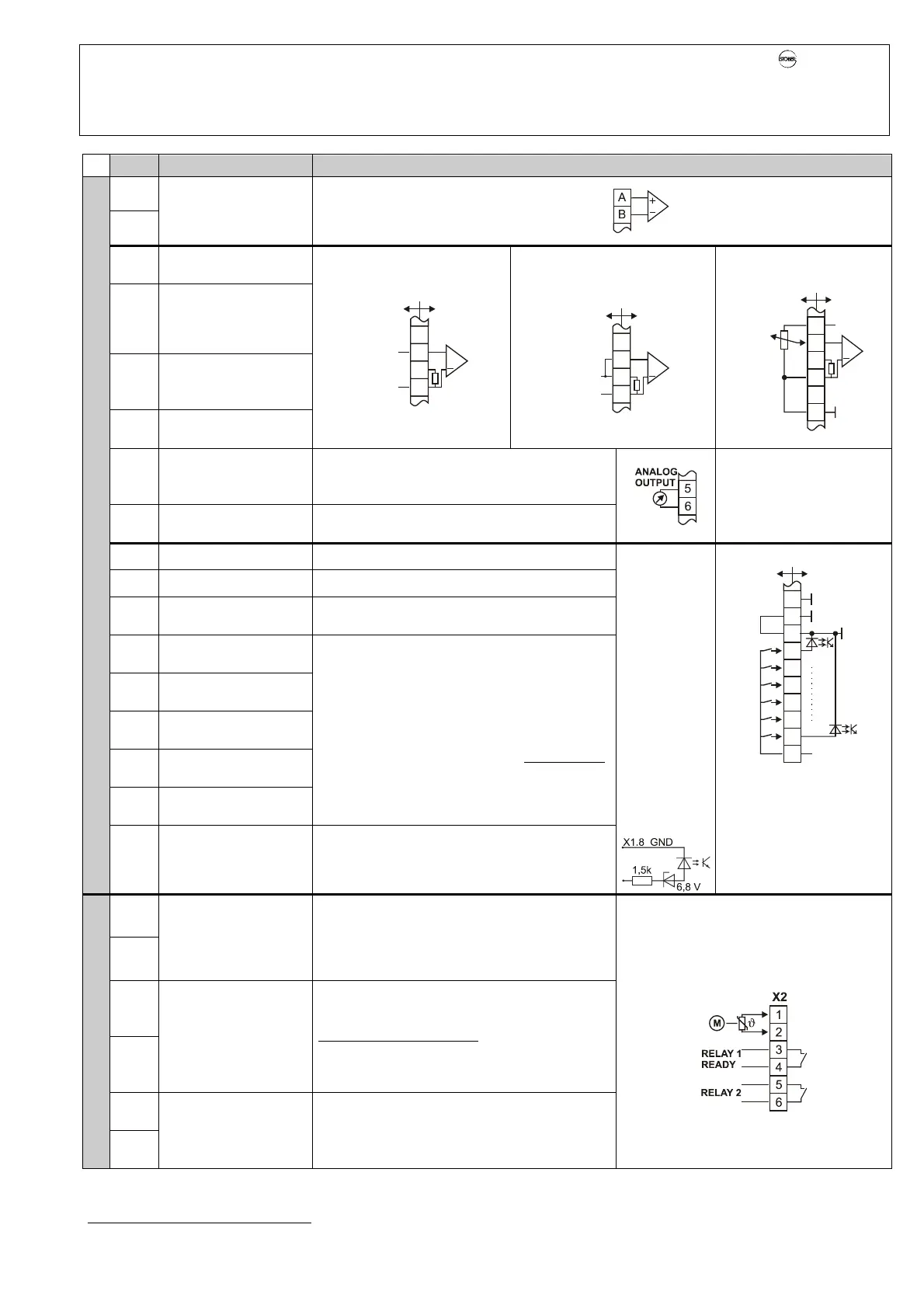
5. Connection Assignment - Control Portion
5
Term.
Function Circuiting
A (+)
B (-)
Analog input AE2
0 to ±10 V
Ri = 25 kΩ,
10bits+sign
T
a
= 4 msec
AE2 function can be programmed under F20
1
Internal voltage supply
+10 V ±5%, max 3 mA
2 (+)
Analog input AE1
0 to ±10 V
Ri = 25 kΩ,
10bits+sign
T
a
= 4 msec
3
Analog input current
0 to ±20 mA
Ri = 510 Ω,
10bits+sign
4 (-)
Analog input AE1,
inverted
External voltage
1
2
3
4
510
Ω
GROUND
±10V
+
AE1 function can be
programmed under F25.
External current
1
2
3
4
510
Ω
GROUND
0 - ±20mA
X1
+
Potentiometer
1
2
3
4
5
6
+10V
max 3mA
NALOG
GROUND
REF.VALUE1
AE1
+
>4k
Ω
510
Ω
5
Analog output
0 to ±10 V, Ri = 1 kΩ
10bits+sign, T
a
= 4 msec
Function can be programmed under F40.
Time constant, low pass, 10 msec
6 Analog ground
Reference potential for terminals A, B and X1.1
to X1.5
7 Ground 12 V Reference potential for terminal X1.15
8 Digital ground Reference potential for inputs X1.9 - X1.14
9
Enable
T
a
= 4 msec
Enable power section. See also param. F38.
Consider halt magnetization (B25, F00=22).
10
Input BE 1
* 8:halt
11
Input BE 2
* 6:Direction of rotation
12
Input BE 3
* 1:RV-select0
13
Input BE 4
* 2: RV-select1
14
Input BE 5
* 0:inactive
Freely programmable, floating inputs. Function
is specified with parameters F31 to F35.
Scan time T
a
= 4 msec. If an incremental
encoder is used, max. input frequency on BE4
to BE5 is 80 kHz. With certain positioning
functions (e.g., Posi:next) BE3 is without delay.
* Default setting of the inverter
Control terminal strip X1
15
Internal voltage
source
1
12 V, 20 mA
Can be used to address binary inputs X1.9 to
X1.14. If so, reference ground of the binary
inputs (X1.8) must be jumpered with 12 V
ground (X1.7).
Tech. data
of binary
inputs:
L level:
< +8 V
H level:
>/= +12 V
Voltage limits:
-10 V
to
+32 V
Interference
immunity
EN 61000-4
1
6
7
8
9
10
13
11
14
12
15
NALOG GND
DIGITA
GND
ENABLE
BE1
BE2
BE3
BE4
BE5
+12V
m
x 2
mA
12 V GND
Important:
With ext. 24 V addressing,
do not insert jumper
between X1.7 and X1.8.
Connect external ground
to X1.8.
1
2
Motor
- Temperature sensor
(PTC)
- Thermal contact
(3.2 V, 1 mA max.)
Connection for one to six positor lines (thermal
motor protection). Lines can be installed with
the motor cable up to 30 m.
If positor lines are not used with a motor,
terminals X2.1 to X2.2 must be jumpered.
3
4
Relay 1
max. 6 A/250 V AC
6 A/30 V DC ohm. load
1 A/30 V DC ind. load,
switching time 15
msec
T
= 4 msec
Indicates that frequency inverter is ready for
operation (i.e., relays closed)
Function can be programmed with F10.
Life expectancy (no. of switches):
Physical: min. of 10,000,000 times
100 000 times at 250 V AC, 6 A
300 000 times at 30 V DC, 2 A (ohm. load)
More frequent signal changeÆUse optional binary outputs!
5
Terminal strip X2
6
Relay 2 (=BA2)
Same tech. spec. as
relay 1
T
a
= 4 msec
Additional relay output, (e.g., for brake control)
Function can be programmed with F00 (= F81).
For brake control, see chap. 8.6.
If a non purely ohmic load is connected,
the relay contacts must be provided with a
protective circuit. Use an external
coupling relay when greater loads must be
switched frequently.
Remarks: T
a
= Scan time
VZ = Sign
1
Short circuit resistance. Caution: A short circuit may cause a processor reset.
external
internal
external internal
external internal
external internal


 To Next Page