STOBER 16 | Appendix
02/2019 | ID 442728.05
239
16.2 Wiring examples
The following chapters show the basic connection using examples.
Information
For UL-compliant operation: The connections marked with PE are intended solely for the
functional grounding.
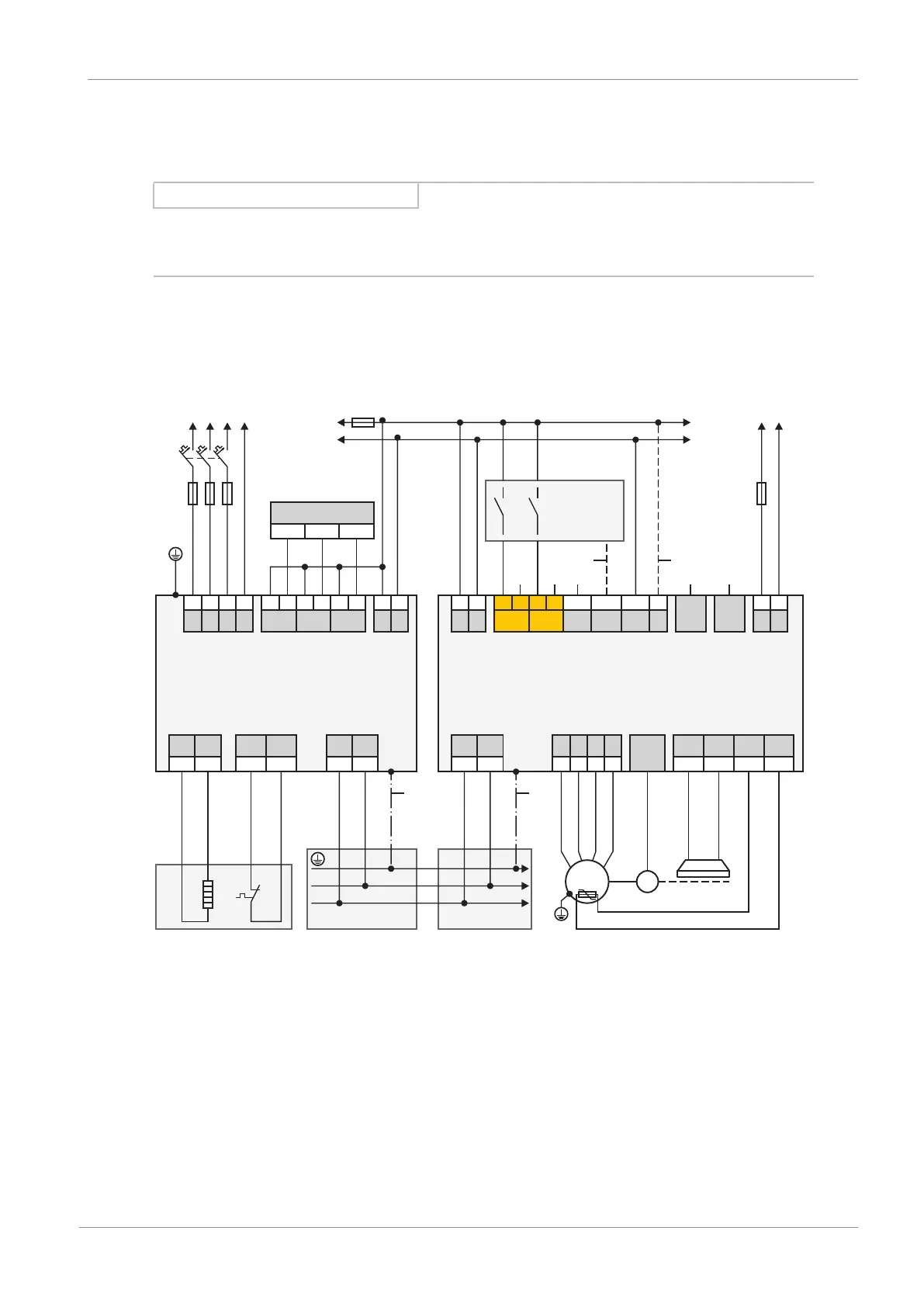
16.2.1 Operation with 1 supply module
The following graphic shows the principal connection of a PS6 supply module and a SI6 drive
controller based on a DC link connection with DL6B Quick DC-Link.
X21
X23
X22
PS6 SI6
X10
X11
X200 X201 X300
X20A
X4A
X2AX22
GND
STO_a STO_b
GND
Vc +
-
+
-
RJ45 RJ45
L1 L2
L3
PE
1 2
3
4
1 2 1 2
3
4
5
6 7 8
1 2
1BD1 1BD2 1TP1
1TP2
1 2 1 2 1 2
RB RB
1TP1 1TP2
D- D+
U
V W PED- D+
5
6 7 8
1 2
3
4
1 2
M
n
X11
+
-
1 2
F3
T2
R1
M1
X100
RDY
WAR1 WAR2
1 2
3
4
5
6
1 2
3
A1
K1
M
DC-
DC+
24 V
DC
M
F4
24 V
DC
2
T1
PEL1 L2
L3
F2
F1
2
11
DL6B DL6B
Digital input
X12 (optional SR6)
STO
status
D-sub
15p
Fig.42: Wiring example with one supply module and one drive controller
A1 Controller
F1 – F4 Fuse
K1 Safety relay
L1 – L3 Three-phase power supply
M Reference ground
M1 Motor
R1 Braking resistor
T1 Supply module
T2 Drive controller
1 Optional connection
2 Spring-loaded contact between DL6B and PS6 or SI6