STOBER 6 | Technical data
02/2019 | ID 442728.05
71
6.10 Choke
Technical specifications for suitable chokes can be found in the following chapters.
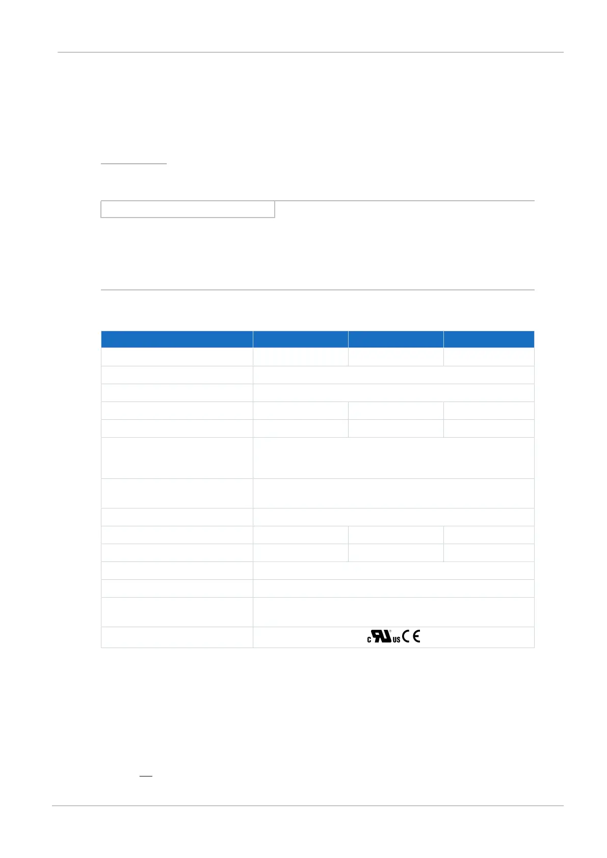
6.10.1 TEP output choke
Output chokes are required for drive controllers of sizes 0 to 2 and for a cable length of 50m or
longer in order to reduce interference pulses and protect the drive system.
Information
The following technical data only applies to a rotating magnetic field frequency of 200Hz. For
example, this rotating magnetic field frequency is achieved with a motor with 4 pole pairs and a
nominal speed of 3000rpm. Always observe the specified derating for higher rotating magnetic
field frequencies. Also observe the relationship with the clock frequency.
Properties
Specification TEP3720-0ES41 TEP3820-0CS41 TEP4020-0RS41
ID No. 53188 53189 53190
Voltage range 3 × 0 to 480V
AC
Frequency range 0 – 200Hz
Nominal current I
N,MF
at 4kHz 4A 17.5A 38A
Nominal current I
N,MF
at 8kHz 3.3A 15.2A 30.4A
Max. permitted motor
cable length with
output choke
100m
Max. surrounding
temperature ϑ
amb,max
40°C
Protection class IP00
Winding losses 11W 29W 61W
Iron losses 25W 16W 33W
Connection Screw terminal
Max. conductor cross-section 10mm²
UL Recognized
Component (CAN; USA)
Yes
Test symbols
Tab. 71: Specification for TEP
Project configuration
Select the output chokes in accordance with the nominal currents of the output chokes, motor
and drive controller. In particular, observe the derating of the output choke for rotating magnetic
field frequencies higher than 200Hz. You can calculate the rotating magnetic field frequency for
your drive with the following formula: