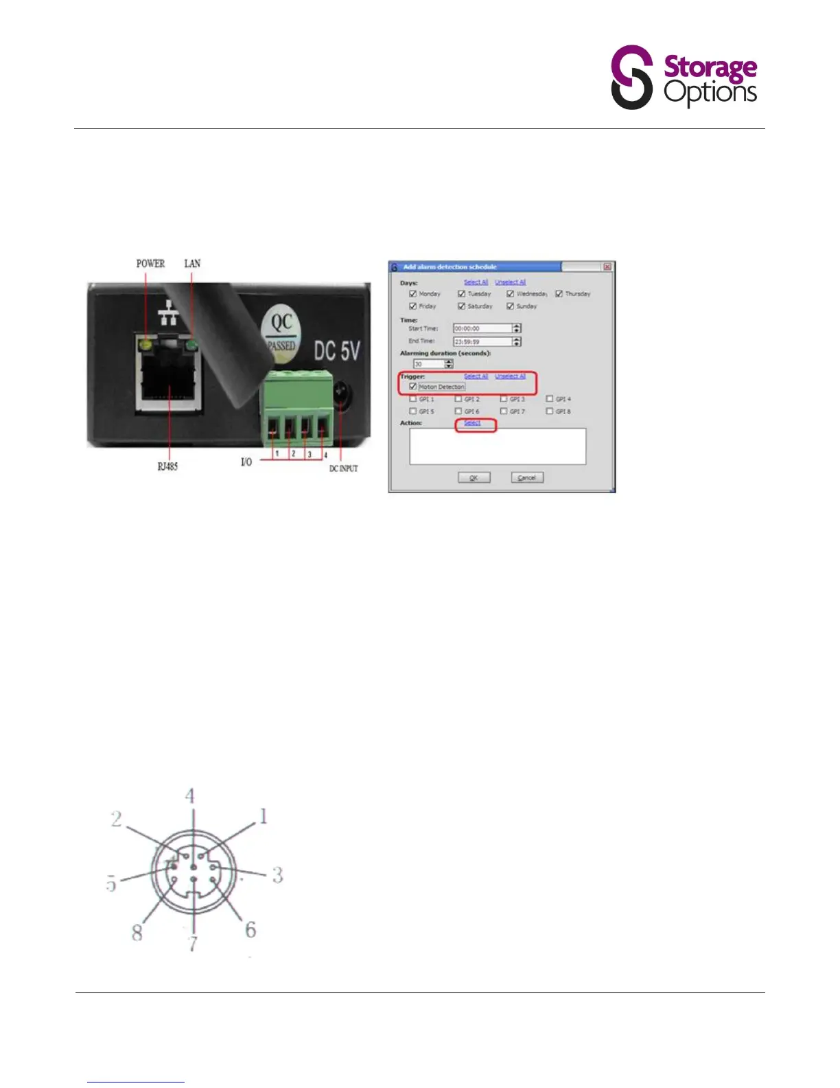
If you wish to connect to the GPIO Alarm interface on the back of the camera, these are the settings.
NB The software may show more GPI pins that on your chosen camera.
Power Supply Light: constant on when power is on
Network light: constant flash when power is on which shows data transmission.
Ethernet interface: RJ-45 interface.
I/O interface: 1 router alarm input, accept 3, 4 two terminals (input terminal grounding, low level effective trigger); 1
router TTL control input, connect 1, 2 two terminals (1, 2 terminals short connections).
Power input interface: connect direct current 5V Power
Extension line interface definition icon:
Power: direct current 12V.
GPIO alarm interface: accept external connection linkage alarm equipment (for example: door magnet, infrared)
Reset line: Short circuit two lines with power off, then power on for 10 seconds to return back default setting
Ethernet interface: RJ-45 network interface.
Backup: follow-up product extend interface.
About GPIO alarm interface (S terminal) definition:
1# +DC12V
2# RS485(A)
3# Earth(GND)
4# IO2 (OUT PUT)
5# RS485 (B)
6# IO1 (IN PUT)
GND: Ground, alarm input ground,RS485 ground
RS485: RS485 control interface, left connection RS485 negative right
connection RS485 positive. connect P/T decoder, support variety PTZ
protocol