Step 3: Connect to the gas supply
1. The inlet to the appliance is
1
⁄2” BSP
internal situated at the right corner
of the rear.
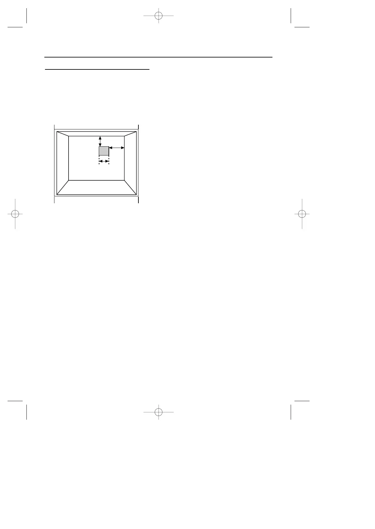
2. Fit the bayonet connection to the
wall in the shaded area as shown.
3. Use a 900mm - 1125mm length of
flexible connector.
The flexible connector shall be
fitted such that it cannot come
into contact with a moveable part
of the housing unit (eg; drawer)
and does not pass through
any space susceptible of becoming
congested.
Make sure that the flexible
connector does not block the
cooling fan inlet.
4. Natural Gas - Flexible connections
should be to BS 669. Parts of the
appliance likely to come into contact
with a flexible connecter have a
temperature rise less than 70˚C.
LP Gas - For flexible connections
use a bayonet type hose, suitable
for use on LP Gas up to 50 mbar
pressure and 70˚C temperature
rise. The flexible hose should be
coloured black with a red stripe,
band or label. If in doubt, contact
your supplier.
5. Rigid connections must be accessible
to disconnect for servicing. Cut a
150mm square hole in the right
hand rear corner of the support
shelf for the supply pipe.
6. Make sure all connections
are gas sound.
24