10
SDM290, SDM280, SDM260 Details
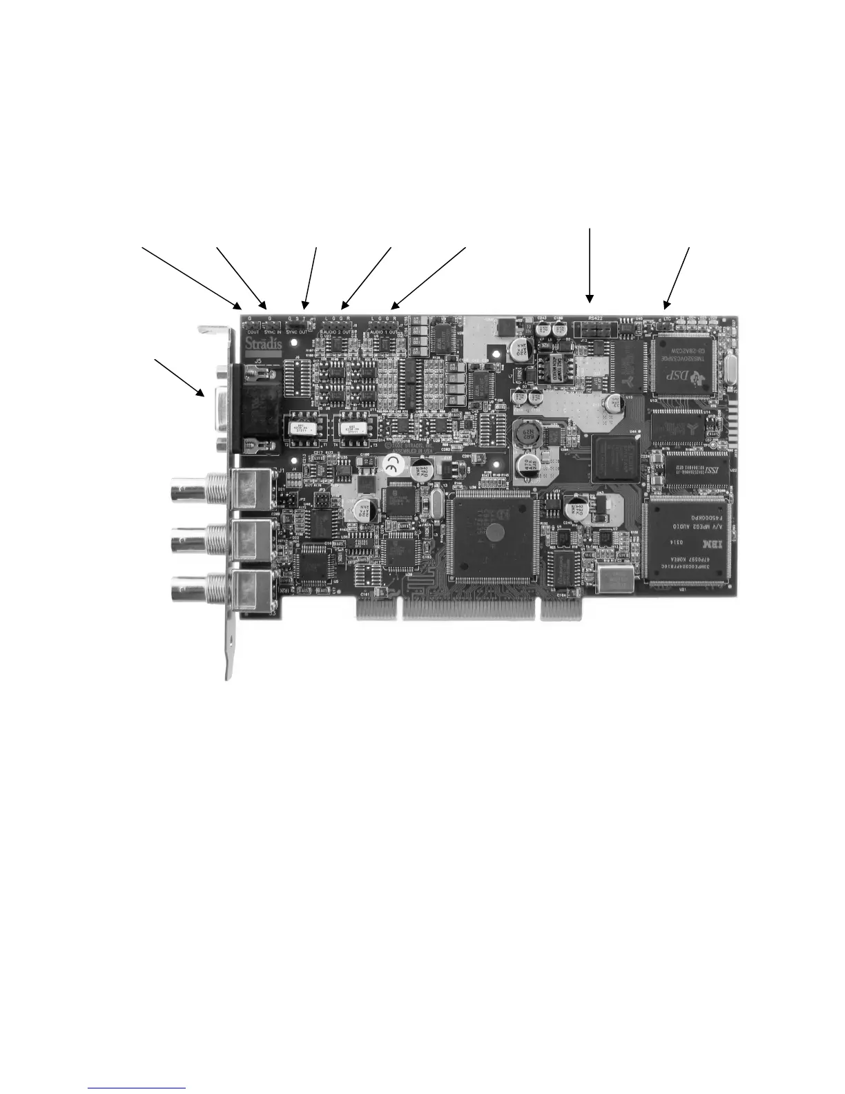
Back Panel and Onboard Connectors
J16 J11 JP1 J8 J7 J12 J13
Composite Sync Sync Out Audio 2 Audio 1 RS-422 Linear Time
Video Out In & 75Ω Term. Out Out (SDM290 only) Code Output
(SDM290 only) (SDM290 only)
Audio
Connector
(see page
14 for pin
outs)
Composite
Video
Output
Sync
Input
SDI
Output
(SDM280
& SDM290
only)
JP1 and J11 are used for sync-in or sync pass-through. JP1 can switch a 75-ohm
terminator in or out. If you have multiple boards in one PC chassis that you wish to
genlock to an outside sync source, set JP1 to Hi-Z by removing the jumper factory
installed between “S” and “T” on the first board. (You may wish to leave the jumper
plugged into “T” only so that it will be available for future use.) Using a SAC012 "Sync
daisy chain cable" plugged into JP1 (“G” is Ground & “S” is Sync), you can then feed
sync to the subsequent boards, J11. Leave JP1 set to 75 Ohms on the last board.
J16 is an unfiltered video output. It is intended for applications where multiple boards
need to be synced together, but not to an external source. Use a SAC012 cable from
J16 on the first board to J11 on the subsequent boards. Additional boards may be
daisy-chained from JP1 to J11. Set the first board (in software) to genlock off and the
other boards to genlock on. All boards will now sync to the first board.
J7 and J8 (SDM290 only) can be used to feed audio into a PC sound card. They are
unbalanced outputs.