9
CAUTION
CAUTIONCAUTION
CAUTION
Observe all ESD precautions. Failure to do so co
Observe all ESD precautions. Failure to do so coObserve all ESD precautions. Failure to do so co
Observe all ESD precautions. Failure to do so could
uld uld
uld
result in damage to the equipment.
result in damage to the equipment. result in damage to the equipment.
result in damage to the equipment.
Hardware Installation
1. Do not remove card from anti-static bag until you are ready to install it.
2. Turn off power to the computer and any device connected to it, such as a
monitor, powered speakers, scanner, etc. Disconnect the power cord from the
wall or uninterruptible power supply.
3. Touch a metal surface on the computer to ground yourself and to discharge any
static electricity.
4. Remove the computer's cover.
5. Locate an unused PCI-Express expansion slot (or PCI slot for legacy models).
6. Remove the metal cover from the back of the computer adjacent to the slot to be
used. Do not lose the screw.
7. While holding the Stradis MPEG-2 Decoder Card by the metal bracket, align it
with the PCI slot and press it down into the connector. Avoid touching the
board’s edge connector. The card must be completely seated into the connector.
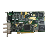
8. The Stradis MPEG-2 Decoder Card can be connected to play audio through the
PC’s sound card. J7 and J8 (SDM290ex, 290e, 290 only) on the upper left
corner of the card are outputs for a sound card for channels 1 and 2. They may
be plugged into an auxiliary input on the PC sound card. (See photographs,
pages 10 & 12.)
9. External sync can be fed into J2 (SDM290ex, 290e, 290, 280ex, 280e, 280,
260ex, 260e and 260), the center BNC connector. To feed sync to additional
cards, or for genlocking cards together, run an SAC012 cable from “SYNC OUT”
to “SYNC IN”. If multiple boards are to be genlocked together, but not to an
external source, designate one board the master. Attach the SAC012 to J16 on
the master board. (See photographs, pages 10 & 12.)
10. Secure the Decoder Card into the expansion slot by replacing the screw
removed in step 6.
11. Replace the computer's cover and reconnect the power cables.
12. Proceed to “Installing the Device Drivers.”