11
On the SDM290 only, J12 is for RS-422 machine control. Connect it to the Stradis
SAC014 or to your own connector. To use the SDM290 as a “Device”, install the cable
with the red (pin 1) line to the right side of the board. To use the SDM290 as a
“Controller”, install the cable with the red (pin 1) line to the left.
J13 is the Linear Time Code output. Use a Stradis SAC014 or your own connector.
Important: Ground is to the left.
S-Video Option
The SDM260, 280, or 290 can be optionally configured to provide a Luma (Y) and
Chroma (CrCb) video output compatible with S-video. In this configuration, J1, the top
BNC connector, becomes the Luma (Y) output, and J2, the middle BCN connector,
becomes the Chroma (CrCb) output. Genlock in is through J11 in this configuration.
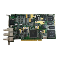
To configure the board for this output, set jumpers JP2 and JP3 as follows:
JP2 JP3
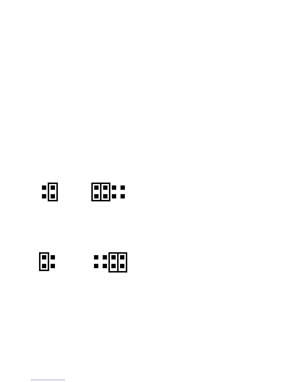
For normal (Composite) operation, jumpers JP2 and JP3 are set as follows:
JP2 JP3