13
Video Output: software configurable
Composite and S Video
Output
NTSC, NTSC-J or PAL
RGB Component
Output
480I/576I RGB
YPbPr Component
Output
480I/576I YPbPr
VideoOutA Composite G Y
VideoOutB Y B Pb
VideoOutC C R Pr
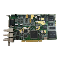
J17 and J18 are the transmitter and receiver components of the Stradis InterDevice
Interface (SIDI) and can be used to sync boards together using a proprietary standard.
These two connectors can be used to frame-lock multiple boards together. They can
even be used to lock an SDM230 to SDM260e or any other card with these connectors.
Future support will be added so that cards can communicate with each other for
synchronization class to run between cards, and over several chassis.
JP1 and J11 are used for sync-in or sync pass-through. JP1 can switch a 75-ohm
terminator in or out. If you have multiple boards in one PC chassis that you wish to
genlock to an outside sync source, set JP1 to Hi-Z by removing the jumper factory
installed between “S” and “T” on the first board. (You may wish to leave the jumper
plugged into “T” only so that it will be available for future use.) Using a SAC012 "Sync
daisy chain cable" plugged into JP1 (“G” is Ground & “S” is Sync), you can then feed
sync to the subsequent boards, J11. Leave JP1 set to 75 Ohms on the last board.
J16 is a buffered copy of the video output on J1 (VideoOutA). Use a SAC012 cable
from J16 on the first board to J11 on the subsequent boards if you wish several boards
to be chroma-locked together. Additional boards may be daisy-chained from JP1 to
J11. Set the first board (in software) to genlock off and the other boards to genlock on.
All boards will now chroma-lock to the first board.
J7 and J8 (SDM290(e)(x) only) can be used to feed audio into a PC sound card. They
are unbalanced outputs.
On the SDM290e(x) only, J12 is for RS-422 machine control. Connect it to the Stradis
SAC014 or to your own connector. To use the SDM290(e)(x) as a “Device”, install the
cable with the red (pin 1) line to the right side of the board. To use the SDM290(e)(x) as
a “Controller”, install the cable with the red (pin 1) line to the left.
J13 is the Linear Time Code output. Use a Stradis SAC014 or your own connector.
Important: Ground is to the left.