130V
120V
,,ov
100V
90V
BCV
t 70V
60V
Ql 50V
g> 40V
-
g 30V
S 20V
& 10V
:,
0
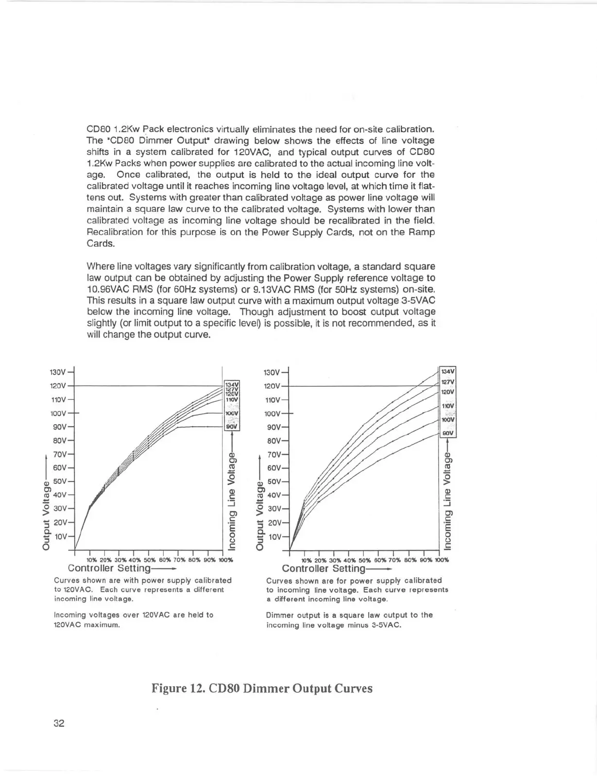
COBO 1.2Kw Pack electronics virtually eliminates the need for on-site calibration.
The
•coao Dimmer Output• drawing below shows the effects of line voltage
shifts in a system calibrated for 120VAC, and typical output curves of COBO
1.2Kw Packs when power supplies are calibrated to the actual incoming line volt-
age. Once calibrated, the output is held to the ideal output curve for the
calibrated voltage until it reaches incoming line voltage level, at which time it flat-
tens out. Systems with greater than calibrated voltage as power line voltage will
maintain a square law curve to the calibrated voltage. Systems with lower than
calibrated voltage as incoming line voltage should be recalibrated in the field.
Recalibration for this purpose is on the Power Supply Cards, not on the Ramp
Cards.
Where line voltages vary significantly from calibration voltage, a standard square
law output can be obtained by adjusting the Power Supply reference voltage to
10.96VAC RMS (for 60Hz systems) or 9.13VAC RMS (for SOHz systems) on-site.
This results in a square law output curve with a maximum output voltage 3-SVAC
below the incoming line voltage. Though adjustment to boost output voltage
slightly (or limit output to a specific level) is possible, it is not recommended, as it
will change the output curve.
130V
120V
,,ov
100V
90V
BCV
Q)
t 70V
C)
n,
60V
.=:
g
Ql 50V
Q)
g> 40V
C:
:.:J
-
C)
g 30V
C:
S 20V
.E
0
& 10V
(.J
:,
,f;
0
Q)
C:
:.:J
C)
C:
.E
0
(.)
,f;
10% 20% 30% 40% 50% BO% 70% BO% 90% 100%
10% 20% 30% 40% 50% BO% 70% 80% 90% 100%
Controller Setting-
c urves shown are with power supply cal ibrated
to
120VAC . Each curve represents a different
incoming line voltage .
Incoming voltages over
120VAC are held to
120VAC maximum .
Controller Setting-
Curves shown are for powe r supply calibrated
to incoming line voltage . Each curve represents
a different incoming line voltage .
Dimmer output is a square law output to the
incom ing line voltage minus
3-SVAC.
Figure 12. CD80 Dimmer Output Curves
32