Do you have a question about the Strand Lighting CD80 and is the answer not in the manual?
Provides troubleshooting information for common system malfunctions and component issues.
Details routine maintenance procedures to ensure optimal system performance.
Contains supplementary information, specifically spare parts.
Lists figures for visual reference and understanding of the equipment.
Provides information on the manual's structure and how to get help.
Offers guidance for technical questions, problems, and parts purchases.
Details the physical and electrical specifications of the CD80 1.2Kw Pack.
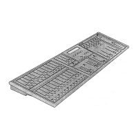
Describes the structural components and assembly of the CD80 1.2Kw Pack chassis.
Explains the electronic components for multiplexed analog input systems.
Details the control module for discreet analog input systems.
Covers the power control and cooling elements within the pack.
Provides instructions for installing and connecting the CD80 1.2Kw Pack.
Guides through the calibration procedures for Ramp Cards and Power Supply Cards.
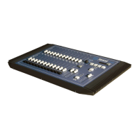
Provides overall physical and operational characteristics of the dimmer pack.
Details operating temperature limits and cooling system for the pack.
Describes ease of serviceability and replaceable electronic components.
Specifies power requirements and configurations for the dimmer pack.
Explains input vs. output characteristics and line/load regulation.
Details output waveform, rise time, efficiency, and capacity.
Outlines overvoltage, overtemperature, and short circuit protection features.
Describes the motherboard, ramp cards, and power supply card for analog input.
Details the control module for discreet analog input systems.
Details SSRs, torroidal chokes, circuit breakers, fan, and power terminal blocks.
Instructions for placing and stacking portable dimmer packs.
Guidelines for mounting the dimmer pack securely to a wall.
Explains how to connect control signals using XLR connectors.
Details setting thumbwheel switches for dimmer number assignment.
Addresses dimmer numbering when using multiple control cables.
Guidance on using different pack types (1.2Kw, 2.4Kw, 6Kw, 12Kw) together.
Describes connecting analog output consoles via DB25 connector.
Explains how to configure phase settings for different power sources.
Instructions for connecting power cables and safety features.
Details indicators and mechanisms for detecting and preventing faults.
Describes using the control panel for testing loads without a console.
States that Ramp Card calibration is factory-done and not typically field-required.
Explains adjusting the Power Supply for voltage references and output curves.
Provides steps for safely removing electronic components for servicing.
Addresses issues affecting multiple dimmers or phases, like power indicators and fan status.
Details malfunctions affecting consecutive dimmers due to Ramp Card issues.
Covers dimmer issues not tied to phase or specific Ramp Cards, like flickering.
| Type | Dimmer |
|---|---|
| Channels | 12, 24, 48 |
| Voltage | 120V, 240V |
| Control Protocol | DMX512 |
| Weight | Varies depending on configuration |
| Output Current | 20A per channel |
| Power per Channel | 2.4kW (120V) |
| Total Power | Varies by configuration |
| Cooling | Forced Air |
| Dimensions | Varies by configuration |